Auger drive for drilling into soil

A technology of auger and land, which is applied in the field of auger to achieve the effect of reducing manufacturing costs

Active Publication Date: 2015-05-27
BAUER MASCH GMBH
View PDF9 Cites 6 Cited by
  • Summary
  • Abstract
  • Description
  • Claims
  • Application Information

AI Technical Summary

Problems solved by technology

However, this is associated with some time consumption, since all spiral passages have to be traversed

Method used


Image

  • Auger drive for drilling into soil
  • Auger drive for drilling into soil

Examples


Embodiment Construction

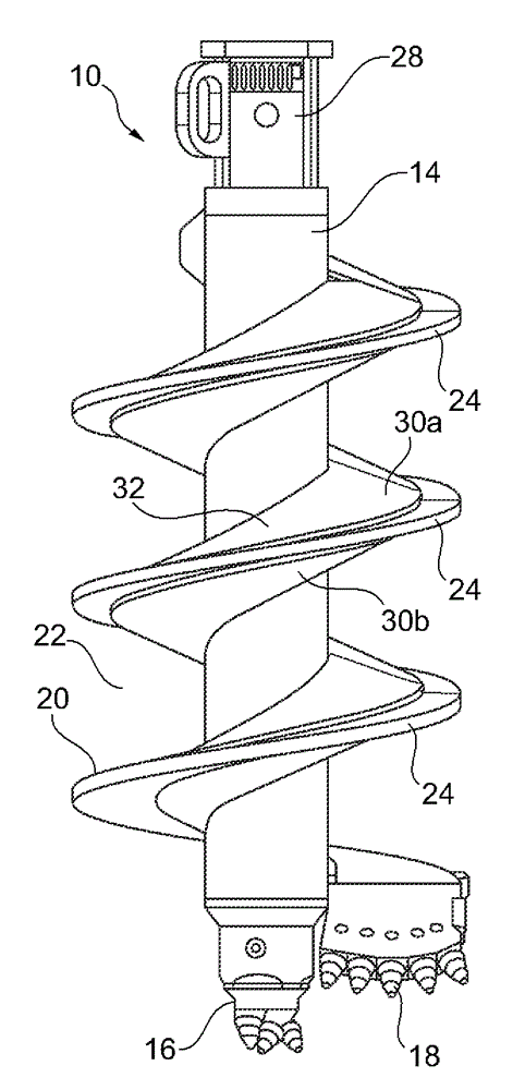
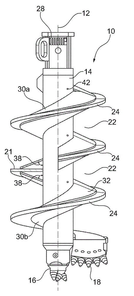
[0025] below with the help of figure 1 with 2 Two exemplary embodiments of an auger 10 according to the invention are schematically shown in FIG. 2 to further illustrate the invention. Due to the largely identical design of the two augers 10 , the description is made directly with reference to the two figures.

[0026] The auger 10 according to the invention has a tubular intermediate rod 14 which is arranged coaxially to the vertical axis 12 . The term “vertical” refers to the usual arrangement of the auger 10 during operation, wherein, in certain cases, it also occurs offset from the vertical and includes an offset of the screw assembly by a few degrees. A pilot 16 is arranged as a centering apex at the lower end of the tubular center rod 14 . Arranged at the upper end is a connecting device 28 which is designed in particular to be connected to a Kelly rod.

[0027] Extending in the radial direction at the lower end of the intermediate rod 14 is an excavating device 18 b...


PUM


Abstract

The invention relates to an auger (10) for Erdbohren with a tubular and to a vertical axis (12) coaxial center shaft (14) and with at least one drill helix (20) from a metal sheet, wherein the drill helix spirally extends around the center shaft and secured thereto, in particular welded, is. According to the invention it is provided that for radial discharge of ground material at the drill helix abgebohrtem a deflection surface (32) is provided, which from 90 DEG different Ableitwinkel (38) in a vertical section to the vertical axis.

Description

technical field [0001] The invention relates to an auger (Bohrschnecke) for ground drilling according to the preamble of claim 1, with a tubular intermediate rod coaxial with the vertical axis and at least one drill body helix comprising a plate ( Bohrwendel), wherein the drill body helix extends helically around the middle rod and is fixed, in particular welded, at the middle rod. Background technique [0002] Augers of this type are used in particular in connection with drilling devices for special subterranean work, for example in order to complete penetrations of foundations. The auger drills into the ground one or more times with the aid of a drilling device until the desired depth is reached. A digging device is arranged at the bottom end of the auger, by means of which the soil awaiting treatment is broken up and broken up. The excavated earth material is conveyed upward by the drill body auger by the rotational movement of the driven auger and stored on the auger b...

Claims


Application Information

Patent Timeline
Patent Type & Authority Applications(China)
IPC IPC(8): E21B10/44E21B10/61
CPCE21B10/44E21B7/005E21B12/06
Inventor J. H. 克拉克森贝格尔M. 施魏格R. A. 布劳恩J. 哈斯
Owner BAUER MASCH GMBH
Why Eureka
Try Eureka