
A disc brake rebound system for an electric vehicle

A kind of brake rebound, electric vehicle technology, applied in the direction of brake actuator, gear transmission mechanism, mechanical equipment, etc., can solve the trouble of brake shoe rebound performance, increase the power consumption of the rider, and the brake rebound is not sensitive enough, etc. problems, to achieve the effect of a wide range of applications, a simple structure, and a large force

Active Publication Date: 2017-04-12
SUQIAN YUDI ELECTRIC VEHICLE
View PDF5 Cites 0 Cited by
  • Summary
  • Abstract
  • Description
  • Claims
  • Application Information

AI Technical Summary

Problems solved by technology

[0002] In the past, the disc brake mechanism was relatively simple. Press the handbrake to drive the oil circuit to lift the brake shoe to the brake disc to achieve the braking effect. However, the rebound performance of the brake shoe has always been a troublesome problem. Usually, it is installed in the handbrake. There is a rebound spring, which uses the resilience of the spring to suck back the oil in the oil circuit, so that the brake shoe leaves the brake disc. However, although this method is relatively mature, it is very limited. Due to the long transmission length of the force, In addition, the oil itself also has a certain compression performance, which leads to the unsatisfactory speed of the brake shoe leaving the brake disc, and the actual time spent on the brake disc is longer than the ideal braking time, which causes more useful work to be lost. In the long run, It will increase the physical exertion of the cyclist, and more seriously, the brake rebound is not sensitive enough, and the brake shoe stays on the brake disc for a long time, even 0.1 second longer, and it is also possible that the tire locks up after braking instantly, causing ACCIDENT

Method used


Image

  • A disc brake rebound system for an electric vehicle

Examples


Embodiment Construction

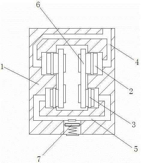
[0014] The preferred technical solutions of the present invention will be described in detail below in conjunction with the accompanying drawings.

[0015] Such as figure 1 As shown, a disc brake rebound system for an electric vehicle of the present invention includes a caliper structure 1 installed on the brake disc, and a pair of oil circuit piston chambers and a pair of gas piston chambers are provided in the caliper structure 1, and a pair of An oil piston 2 is arranged in each of the oil piston chambers, and a gas piston 3 is respectively arranged in a pair of gas piston chambers. The brake disc is located between the pair of oil pistons 2 and the pair of gas pistons 3. The brake oil pipe 4 is connected to the oil piston chamber, and the gas passage 5 is connected to the pair of gas piston chambers. The oil passage piston 2 and the gas piston 3 on the same side are connected by the brake shoe 6. Pressure air groove, the spring air plug 7 that is used for sucking in and p...


PUM


Abstract

The invention discloses a disc brake resilience system for an electrombile. The disc brake resilience system comprises a clamp structure arranged on a brake disc, wherein a pair of oil way piston cavities and a pair of gas piston cavities are formed in the clamp structure, wherein an oil way piston is arranged in each of the pair of oil way piston cavities; a gas piston is arranged in each of the pair of gas piston cavities; the brake disc is positioned between the pair of oil way pistons and the pair of gas pistons; a brake oil way pipe is connected to the pair of oil way piston cavities; a gas channel is connected to the pair of gas piston cavities; the oil path pistons and the gas pistons which are positioned on the same side are connected by brake shoes; a negative pressure gas tank is formed in the gas channel; a spring gas plug for pumping and exhausting gas is arranged in the negative pressure gas tank. Compared with the prior art, the disc brake resilience system for the electrombile, disclosed by the invention, has the advantages that the resilience force of a hand brake can be increased, and slow response of a spring in the hand brake is avoided; the conditions that the brake is insensitive and dynamic idle work is increased due to the fact that the brake shoes stagnate on the brake disc are prevented.

Description

technical field [0001] The invention relates to a braking auxiliary tool for a non-motor vehicle, in particular to a disc brake rebound system for an electric vehicle. Background technique [0002] In the past, the disc brake mechanism was relatively simple. Press the handbrake to drive the oil circuit to lift the brake shoe to the brake disc to achieve the braking effect. However, the rebound performance of the brake shoe has always been a troublesome problem. Usually, it is installed in the handbrake. There is a rebound spring, which uses the resilience of the spring to suck back the oil in the oil circuit, so that the brake shoe leaves the brake disc. However, although this method is relatively mature, it is very limited. Due to the long transmission length of the force, In addition, the oil itself also has a certain compression performance, which leads to the unsatisfactory speed of the brake shoe leaving the brake disc, and the actual time spent on the brake disc is lon...

Claims


Application Information

Patent Timeline
Patent Type & Authority Patents(China)
IPC IPC(8): F16D65/14F16D121/02F16D125/08
Inventor 朱源
Owner SUQIAN YUDI ELECTRIC VEHICLE
Learn More