A vernier type comprehensive gauge for holes
A technology for gauges and holes, applied in the field of vernier-type comprehensive gauges for holes, can solve problems such as no significant advantages, and achieve the effects of improving measurement accuracy, improving work efficiency, and improving operation convenience and work efficiency.
- Summary
- Abstract
- Description
- Claims
- Application Information
AI Technical Summary
Problems solved by technology
Method used
Image
Examples
Embodiment 1
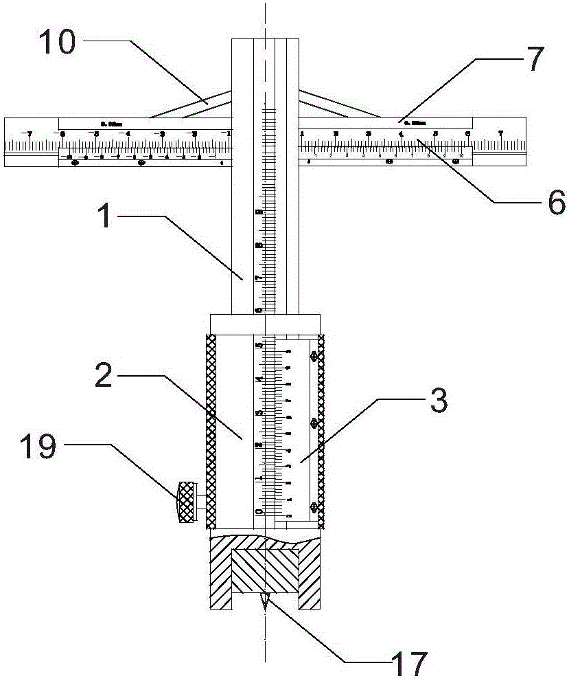
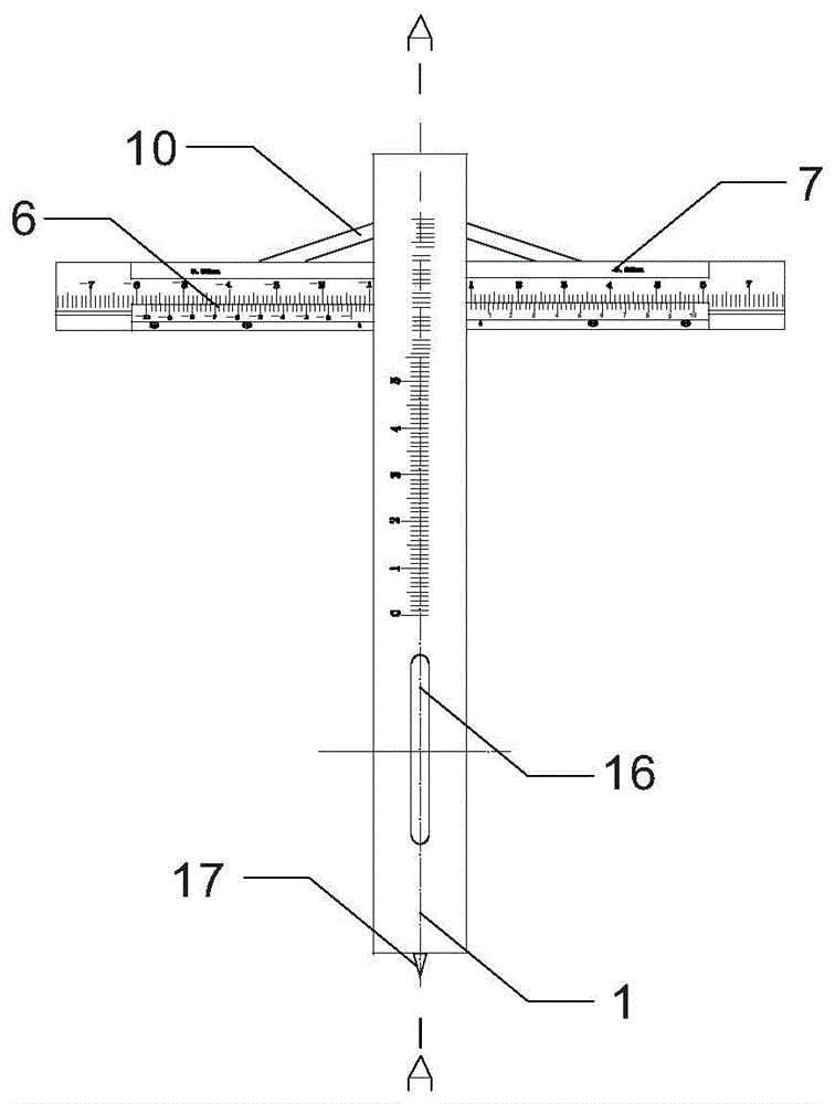
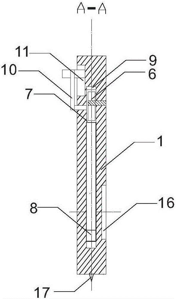
[0028] Such as Figure 1 to Figure 6 As shown, a vernier-type comprehensive gauge for holes includes a gauge body 1 with scale marks, a handle reference block 2, a vernier ruler 3 and an aperture measuring mechanism arranged on the gauge body, and the graduation value on the gauge body 1 is 1 mm , the division value on vernier ruler 3 is 0.02mm. The handle reference block 2 is a cylinder, and its outer diameter is 30 mm, which is larger than the aperture of a commonly used machining hole, so that it is convenient to support the handle reference block 2 at the orifice. The main body of the gauge body 1 is also a cylinder, the cross-sectional diameter of the gauge body 1 is 18 mm, the central angle of the vernier ruler embedded opening 5 on the peripheral surface of the handle reference block 2 is 90°, and the vernier ruler 3 is in the shape of an arc tile, The outer peripheral surface of the gauge body 1 coincides with the inner concave surface of the vernier ruler 3 . The ha...
Embodiment 2
[0031] Such as Figure 7 to Figure 11 As shown, the cross-sectional diameter of the gauge body 1 is 14 mm. The central angle of the vernier ruler insertion opening 5 on the peripheral surface of the handle reference block 2 is 180°. The aperture measurement mechanism also includes a central sliding rod 12, an upper four-bar linkage 13 and a lower four-bar linkage 14, and a radially penetrating notch 9 is provided between the two ends of the gauge body 1, and the notch 9 does not pass through. At both ends of the gauge body 1, a sliding rod slot 18 is provided on the inner wall of the notch 9 along the axial direction of the gauge body 1. The sliding rod slot 18 runs through the top of the gauge body 1. The cross section of the sliding rod slot 18 is square. The cross section of the central sliding rod 12 is also square, and the central sliding rod 12 is adapted to slide and be arranged in the sliding rod slot 18 to realize the sliding connection with the gauge body 1, and the...
Embodiment 3
[0034] The central angle of the vernier ruler insertion port 5 on the peripheral surface of the handle reference block 2 is 270°. All the other are with embodiment 1.
PUM
 Abstract
Description
Claims
Application Information
 - R&D
- Intellectual Property
- Life Sciences
- Materials
- Tech Scout
- Unparalleled Data Quality
- Higher Quality Content
- 60% Fewer Hallucinations
Browse by: Latest US Patents, China's latest patents, Technical Efficacy Thesaurus, Application Domain, Technology Topic, Popular Technical Reports.
© 2025 PatSnap. All rights reserved.Legal|Privacy policy|Modern Slavery Act Transparency Statement|Sitemap|About US| Contact US: help@patsnap.com


