

Electromagnetic scattering analysis method for ultra-high-speed thin-coated stealth flying targets
A flying target, electromagnetic scattering technology, applied in electrical digital data processing, instruments, calculations, etc., can solve problems such as a lot of computing time and memory, large unknowns in electromagnetic scattering, etc., to achieve fast solution speed, few unknowns, and acceleration matrix. The effect of solving
Active Publication Date: 2018-04-03
NANJING UNIV OF SCI & TECH
View PDF4 Cites 0 Cited by
- Summary
- Abstract
- Description
- Claims
- Application Information
AI Technical Summary
Problems solved by technology
However, using the above methods to analyze the electromagnetic scattering problem of ultra-high-speed thin-coated stealth flying targets faces the problem of large unknowns, which leads to the need for a lot of computing time and memory in the solution process.
Method used
View moreImage
Smart ImageViewing Examples

Examples
Embodiment Construction
Login to View More PUM
| Property | Measurement | Unit |
|---|---|---|
| radius | aaaaa | aaaaa |
| thickness | aaaaa | aaaaa |
| thickness | aaaaa | aaaaa |
Abstract
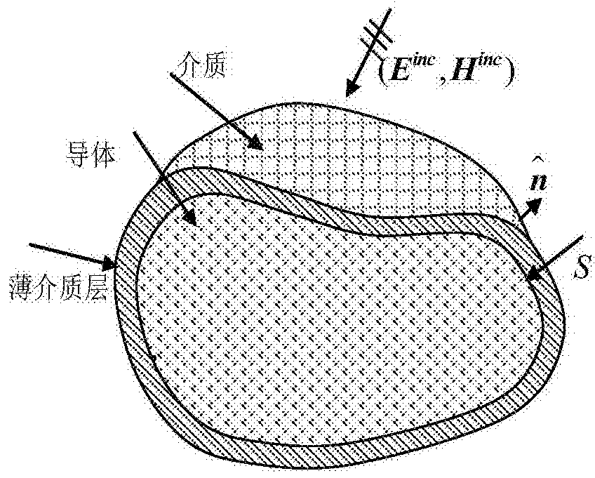
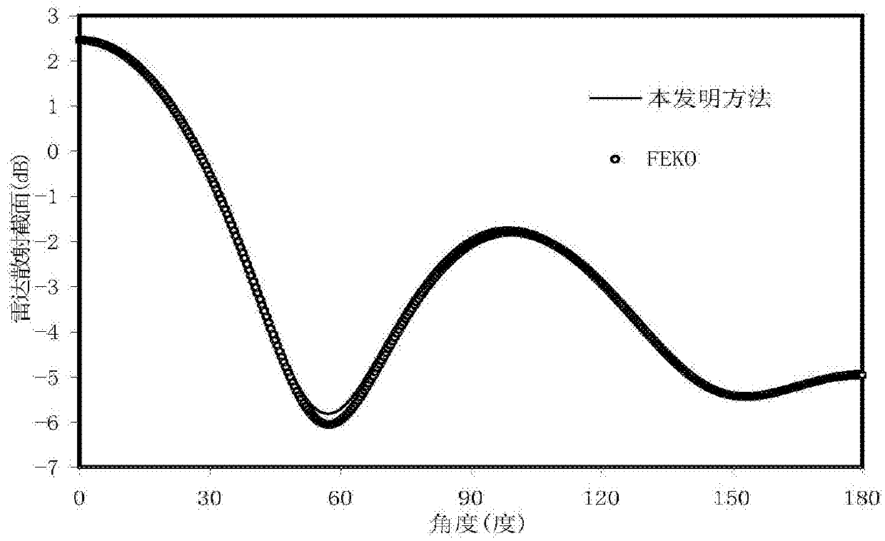
The invention discloses an electromagnetic scattering analysis method of an ultra-high-speed thin-coated stealth flying target. Aiming at the non-uniform characteristics of the plasma wrapped around the ultra-high-speed thin-coated stealth flying target, the volume integral equation method is used to analyze the metal body of the stealth flying target and the stealth material coated by thin coating analysis based on area integral method for modeling analysis. Compared with the traditional method in which volume integral equations are used for all medium parts, the method of the present invention can save computing resources, and at the same time, because the Green's function used in the equation is the Green's function in vacuum, the multi-layer fast multi-level sub-technology is used The solution is further accelerated, so that the present invention requires less computing memory and computing time for solving the scattering problem of ultra-high-speed thin-coated stealth flying targets.
Description
Electromagnetic Scattering Analysis Method of Ultra-high Speed Thin Coated Stealth Flying Target technical field The invention belongs to the technical field of rapid calculation of target electromagnetic scattering characteristics, in particular to an electromagnetic scattering analysis method applied to ultra-high-speed thin-coated stealth flying targets. Background technique Due to the high flight speed (above Mach 3) and high flight altitude (above 20Km) of the ultra-high-speed flying target, the friction with the air during its flight will generate aerodynamic heat of several thousand degrees Celsius, making the surrounding air appear ionized. The ionic state exists. When the degree of ionization reaches a certain level, the ionized gas has plasma properties. At this time, the enveloping flow field near the surface of the flying target is usually called plasma enveloping flow field, re-entry plasma or plasma sheath, which means that the flying target is covered by ...
Claims
Login to View More Application Information
Patent Timeline
 Patent Type & AuthorityPatents(China)
IPC IPC(8): G06F17/50
Inventor陈如山丁大志樊振宏陶诗飞
OwnerNANJING UNIV OF SCI & TECH