Determining method for exhaust mass flow of spacecraft under low pressure in cabin

A technique for determining the method and mass flow, which can be used in instruments, special data processing applications, electrical digital data processing, etc., and can solve the problems of inability to give exhaust mass flow and low Reynolds number.

Active Publication Date: 2015-05-27
CHINA ACAD OF AEROSPACE AERODYNAMICS
View PDF4 Cites 8 Cited by
  • Summary
  • Abstract
  • Description
  • Claims
  • Application Information

AI Technical Summary

Problems solved by technology

For the exhaust problem under low cabin pressure, due to the low Reynolds number of the flow, the viscous effect can be comp

Method used


Image

  • Determining method for exhaust mass flow of spacecraft under low pressure in cabin
  • Determining method for exhaust mass flow of spacecraft under low pressure in cabin
  • Determining method for exhaust mass flow of spacecraft under low pressure in cabin

Examples


Embodiment Construction

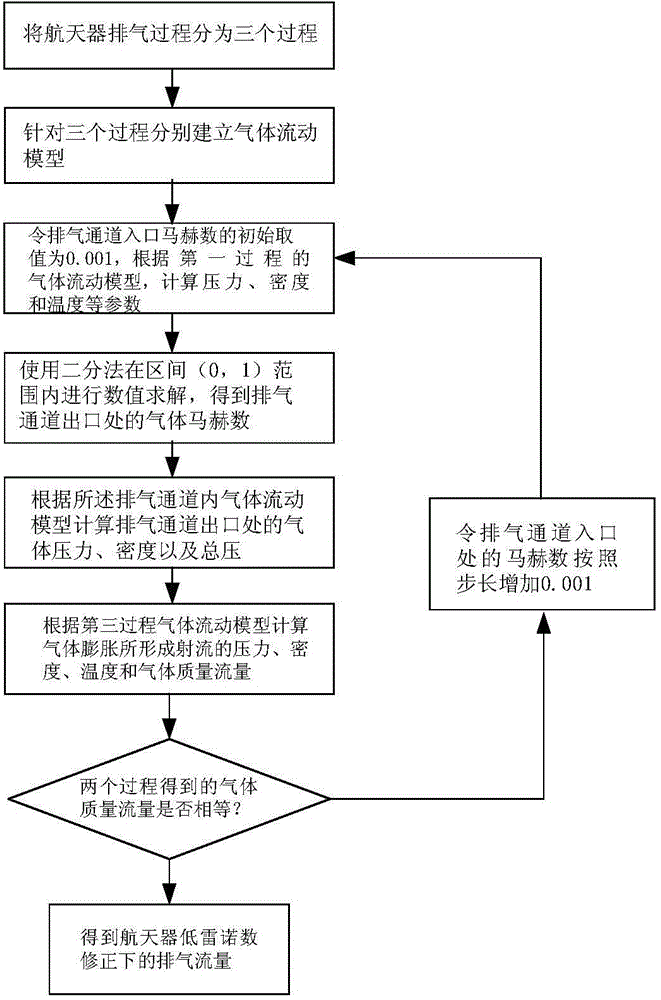
[0032] Such as figure 2 As shown, the present invention provides a method for determining the mass flow rate of spacecraft exhaust under low cabin pressure, the steps are as follows:

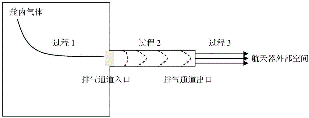
[0033] (1) if figure 1 As shown, the spacecraft exhaust process is divided into three parts: the first process is a one-dimensional isentropic flow process (process 1) where the gas flows from the cabin to the entrance of the exhaust channel on the bulkhead; the second process is the pipeline flow process (process 2) from the inlet of the exhaust channel to the outlet of the exhaust channel considering friction; the third process is the one-dimensional isentropic flow process from the outlet of the exhaust channel to the outer space of the spacecraft ( Process 3): The cross-section of the exhaust channel is circular, and the diameters of each part of the exhaust channel are the same.

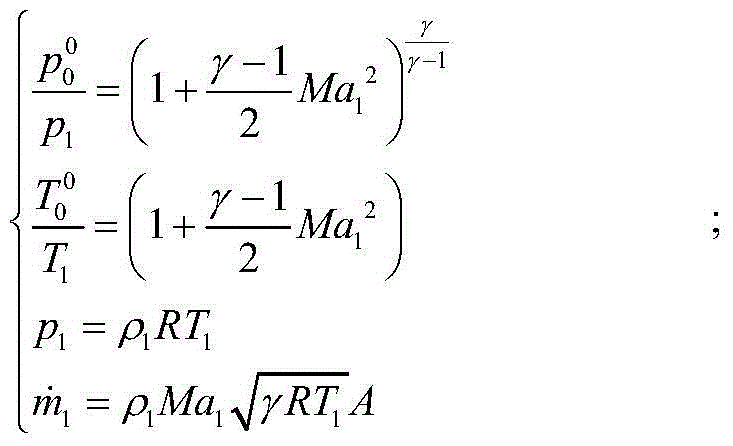
[0034] (2) Establish a gas flow model in the spacecraft cabin for the first process, specifically:

[0035]...


PUM


Abstract

The invention discloses a determining method for exhaust mass flow of a spacecraft under the low pressure in a cabin. Under the condition of the low pressure in the cabin, the length of an exhaust channel and viscous loss of gas flowing in the channel cannot be neglected. The flowing of one-dimensional isentropic flows and pipeline flowing considering the friction are coupled, and a coupling computation cabin for the exhaust mass flow of the spacecraft under the low pressure in the cabin is established. The iterative solving is performed on the coupling model to obtain the exhaust mass flow by adopting a method of traversing channel inlet Mach number, so the problem that the exhaust mass flow is difficult to obtain under the low pressure in the cabin is solved.

Description

technical field [0001] The invention relates to a method for determining the exhaust gas mass flow rate of a spacecraft under low cabin pressure, and belongs to the technical field of spacecraft aerodynamics. Background technique [0002] During the launch of a non-airtight spacecraft, as the height increases, the pressure outside the cabin continues to decrease. In order to ensure that the pressure difference between the inside and outside of the cabin can be maintained within the allowable range, it is necessary to design an exhaust channel on the surface of the aircraft to keep the cabin The internal gas is discharged to ensure the structural safety of the aircraft. [0003] Theoretically, the exhaust process can be finely simulated using the unsteady computational fluid dynamics method, but after examining the characteristic time of the exhaust process, it is found that the computational fluid dynamics method is not feasible. Assume that the diameter of the exhaust chan...

Claims


Application Information

Patent Timeline
IPC IPC(8): G06F19/00
Inventor 陈智苗文博张亮程晓丽
Owner CHINA ACAD OF AEROSPACE AERODYNAMICS
Why Eureka
Try Eureka