Driving device and method of semiconductor light emitter group
A technology of light-emitting devices and driving devices, which can be applied to lighting devices, electroluminescent light sources, light sources, etc., and can solve the problems of insufficient speed of the feedback regulation loop, inability to adjust the impulse current, and damage to the lifespan.
- Summary
- Abstract
- Description
- Claims
- Application Information
AI Technical Summary
Problems solved by technology
Method used
Image
Examples
no. 1 example
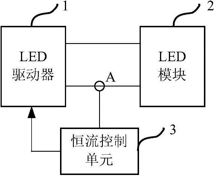
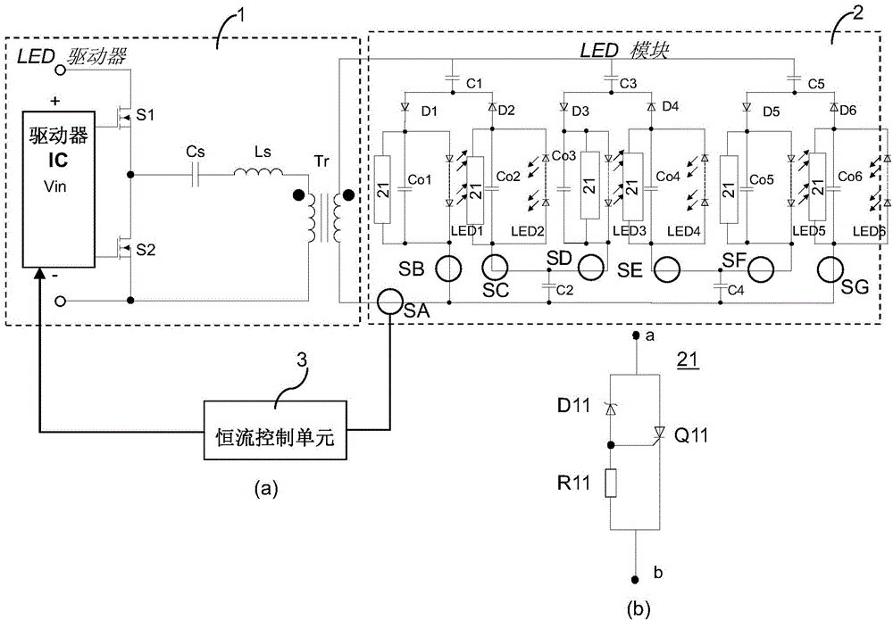
[0068] The following will refer to Figure 6 A more detailed circuit embodiment of driving the LED module 12 by using the driving device of the present application is described, in which the circuit structures of the constant current control unit 13 and the instant control unit 14 are specifically shown.
[0069] Such as Figure 6 As shown, the driving device according to the first embodiment of the present application includes an LED driving unit 11 connected to an LED module 12 for driving the LED module 12 . Since the structures of the LED drive unit 11 and the LED module 12 are the same as those referred to above Figure 5 The structure described is the same, so it will not be repeated here.
[0070] further reference Figure 6 , the driving device according to the first embodiment of the present application may further include a constant current control unit 13, and the constant current control unit 13 includes a current sensing part (that is, an AVG value sensing part...
no. 2 example
[0077] Different from the first embodiment in which the output of the LED driving unit 11 is controlled by adjusting the frequency, the second embodiment of the present application controls the output of the LED driving unit 111 by adjusting the duty cycle.
[0078] Such as Figure 9 As shown, the driving device according to the second embodiment of the present application includes an LED driving unit 111, a constant current control unit 13 and an instant control unit 14. The LED driving unit 111 is connected to the LED module 12 for driving the LED module 12. The constant The flow control unit 13 and the immediate control unit 14 are connected between the LED driving unit 111 and the LED module 12 to control the LED module 12 in feedback. Since the structures of the LED module 12, the constant current control unit 13 and the instant control unit 14 here are the same as those referred to above Figure 6 The structure described is the same, so it will not be repeated here.
...
no. 3 example
[0082] The above-mentioned first and second embodiments are examples of adjusting the output of the LED drive unit by controlling the operating frequency and duty cycle of the drive signal of the switching element in the drive unit by using an analog circuit method, according to the third implementation of the present application In this example, the digital signal processing unit will be used to control the operating frequency or duty cycle of the driving signal of the switching element in the driving unit, and then adjust the output of the LED driving unit.
[0083] Such as Figure 10 As shown, the driving device according to the third embodiment of the present application includes an LED driving unit 11 and an LED module 12 , and the LED driving unit 11 is connected to the LED module 12 for driving the LED module 12 . Since the structures of the LED driving unit 11 and the LED module 12 here are the same as those referred to above Figure 5 The structure described is the s...
PUM
 Abstract
Description
Claims
Application Information
 - R&D
- Intellectual Property
- Life Sciences
- Materials
- Tech Scout
- Unparalleled Data Quality
- Higher Quality Content
- 60% Fewer Hallucinations
Browse by: Latest US Patents, China's latest patents, Technical Efficacy Thesaurus, Application Domain, Technology Topic, Popular Technical Reports.
© 2025 PatSnap. All rights reserved.Legal|Privacy policy|Modern Slavery Act Transparency Statement|Sitemap|About US| Contact US: help@patsnap.com


