Contactless charging system for charging a motor vehicle battery

A battery and automobile technology, applied in the direction of electric vehicle charging technology, battery circuit device, battery/fuel cell control device, etc., can solve problems such as no solution mentioned

Active Publication Date: 2015-05-27
RENAULT SA
View PDF4 Cites 8 Cited by
  • Summary
  • Abstract
  • Description
  • Claims
  • Application Information

AI Technical Summary

Problems solved by technology

However, there is no mention of a solution in case the relays of the battery are disconnected due to a fault

Method used


Image

  • Contactless charging system for charging a motor vehicle battery
  • Contactless charging system for charging a motor vehicle battery
  • Contactless charging system for charging a motor vehicle battery

Examples


Embodiment Construction

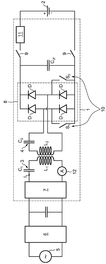
[0034] figure 1 A system 1 for contactless charging of a battery 2 of a motor vehicle according to an exemplary embodiment of the invention is shown.

[0035] The contactless charging system 1 comprises a primary inductive circuit 3 installed underground (eg in a parking space) and a secondary inductive circuit 4 vehicularly installed on the car.

[0036] The primary induction circuit 3 is coupled via a rectification stage 6 and an inverter 7 to an electric power supply network 5 supplying the power required by the secondary induction circuit 3 . The secondary sensing circuit 4 is coupled to the battery 2 via a bridge rectifier 8 and two relays 9 each coupled to a terminal of the battery 2 . These relays 9 can be opened in the event of an electrical failure of the vehicle, which allows the battery 2 to be electrically decoupled from the secondary induction circuit 4 .

[0037] The secondary inductive circuit 3 and the secondary inductive circuit 4 each comprise a correspondi...


PUM


Abstract

A contactless charging system (1) for charging a motor vehicle battery (2) comprising a primary induction circuit (3) outside the motor vehicle powered by an electric power network (5), and a secondary induction circuit (4) installed on the motor vehicle and coupled to the battery (2) via a rectifier bridge (8). It comprises controlled switch means (10) capable of putting the secondary induction circuit (4) into short circuit without putting the battery (2) into short circuit when there is an electrical malfunction on board the motor vehicle, and control means capable of cutting off power to the primary induction circuit (3) when they detect a short circuit in the secondary induction circuit (4).

Description

technical field [0001] The present invention relates to the contactless charging of the battery of an automobile, and more particularly to the safety of the automobile in the event of an electrical failure during the contactless charging of the battery. Background technique [0002] A system for contactless charging of a vehicle's battery generally takes the form of a primary inductive circuit underground and a secondary inductive circuit mounted on the vehicle. Energy transfer occurs between these two inductive circuits by electromagnetic induction. Such a charging system offers the following advantages over charging systems with sockets: On the one hand, the fact that there are no forgotten connections or any constraints associated with the weight of the plug allows for improved user comfort and human engineering. On the other hand, positioning errors of the charging system are allowed and an efficiency equal to that of the wired charging system is obtained. Finally, th...

Claims


Application Information

Patent Timeline
Patent Type & Authority Applications(China)
IPC IPC(8): B60L3/04B60L11/18H02H3/087H02J7/02H02H3/02H02H7/18
CPCB60L3/04H02H3/023H02H3/087H02H7/18B60L15/007B60L2210/30Y02T90/12Y02T10/7072Y02T90/14B60L53/22B60L53/36B60L58/12B60L53/122H02J2310/48Y02T10/64Y02T10/70Y02T10/72H02J7/00304H02J50/12B60L53/12
Inventor J·乌伊维H·多芬
Owner RENAULT SA
Why Eureka
Try Eureka