Window structure body

A structure and planar light-emitting technology, applied in parallel glass structures, windows/doors, building components, etc., can solve problems such as difficult building materials, achieve good durability, ensure strength, and be easy to maintain.

Inactive Publication Date: 2015-05-27
MIRAI KIKAKU
View PDF7 Cites 8 Cited by
  • Summary
  • Abstract
  • Description
  • Claims
  • Application Information

AI Technical Summary

Problems solved by technology

The main material of the light guide plate is resin material such as acrylic, because it is a combustible material, it is difficult to be used as a building material, and it is directly used for the main opening without treatment.

Method used


Image

  • Window structure body
  • Window structure body
  • Window structure body

Examples


Embodiment 1

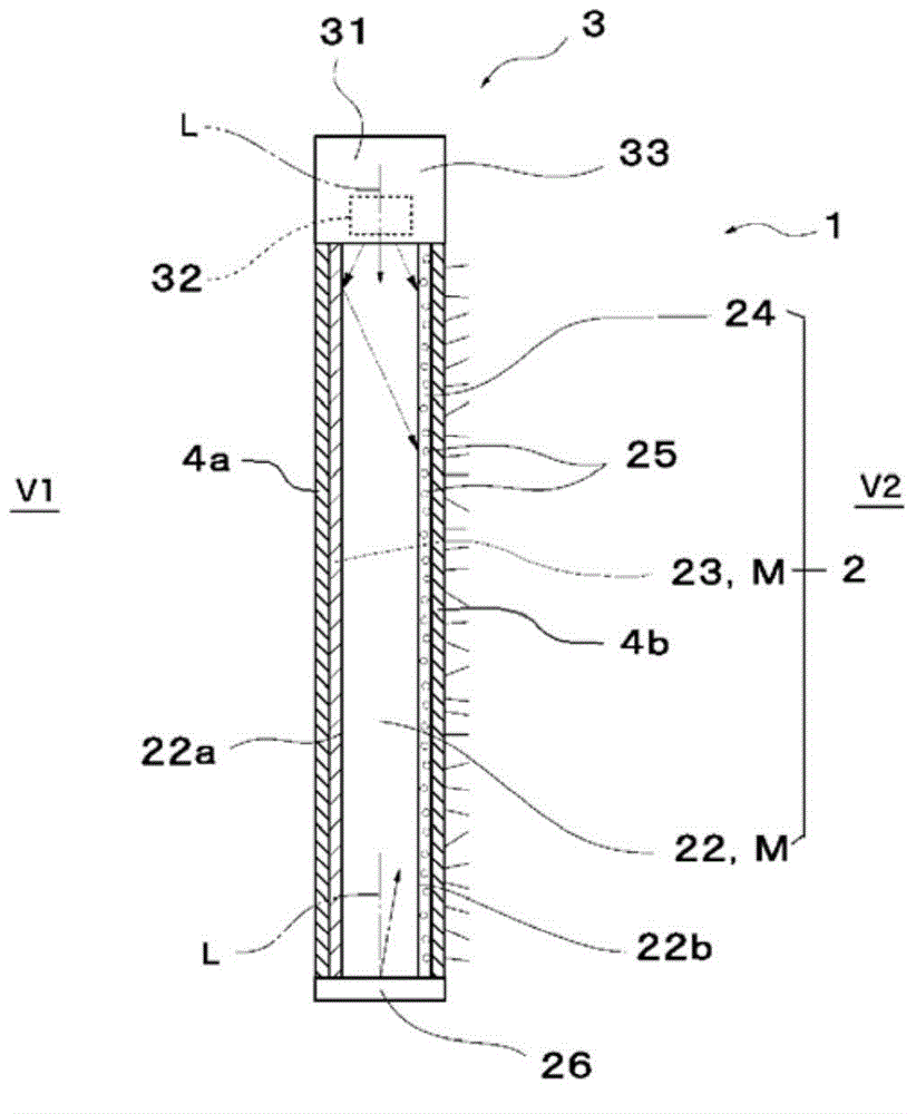
[0060] figure 1 It is a schematic view of the window structure 1 of the present invention viewed from a cross section. The window structure 1 of the present embodiment includes a planar light emitting body part 2 , its light emitting device part 3 , and glass plates 4 a and 4 b that protect the inside and outside of the planar light emitting body part 2 .

[0061] The planar light emitter part 2 includes a base material 22 made of a translucent resin plate. Although not shown, the substrate 22 is figure 1 Viewed from the right or left side, form a rectangular shape. As the base material 22, acrylic resin, polycarbonate, polyvinyl chloride, etc. can be used.

[0062] The base material 22 may be colorless and transparent, or may be colored and transparent. The metal thin film layer 23 is laminated on the inner surface (V1 side) of the base material 22 .

[0063] The metal thin film layer 23 is a thin film layer provided so as to have a predetermined light transmittance (lig...

Embodiment 2

[0085] based on figure 2 Another embodiment will be described. For convenience of description, this embodiment is the second embodiment. This embodiment relates to a window structure and is basically based on the first embodiment. The same reference numerals are assigned to the same parts as those in the first embodiment, and description thereof will be omitted.

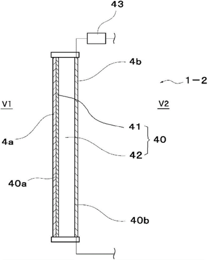
[0086] figure 2 It is a schematic view of the window structure 1-2 viewed from the cross section. The window structure 1 - 2 of the present embodiment has a planar light emitting body 40 and glass plates 4 a and 4 b that protect the inside and outside of the planar light emitting body 40 .

[0087] The planar light emitter unit 40 has a transparent organic EL lighting panel 42 and a control circuit 43 on which a metal thin film layer 41 is laminated on the inner surface side (V1 side). The control circuit 43 controls the voltage applied to the organic EL lighting panel 42 . When no voltage is applied to the o...

Embodiment 3

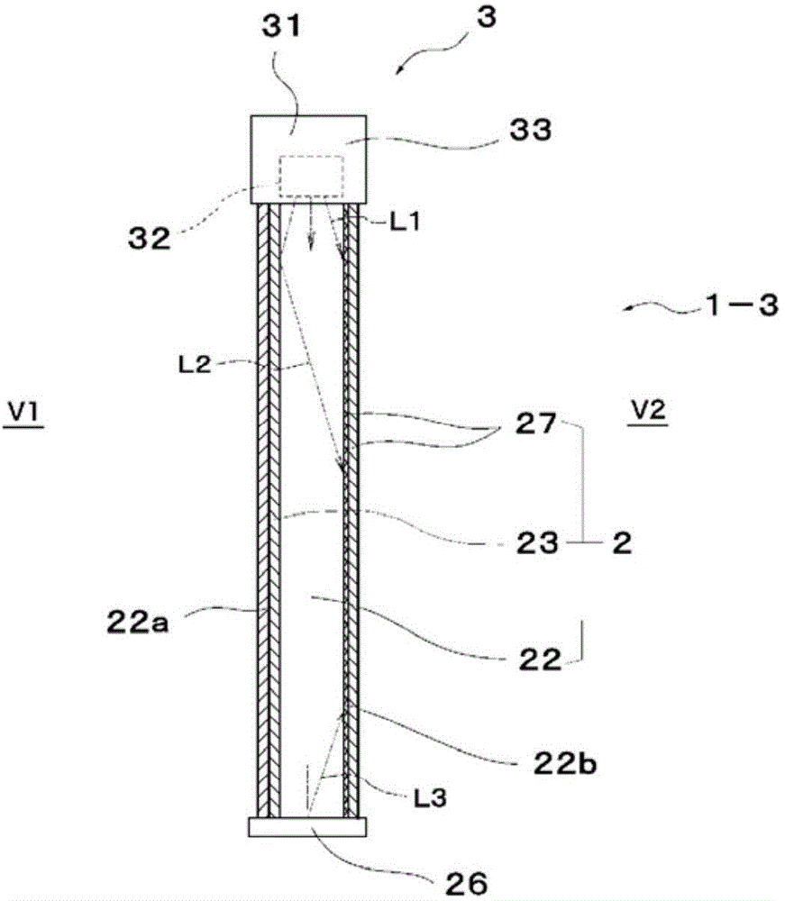
[0091] image 3 It is a schematic view of the window structure 1-3 viewed from the cross section. The window structure 1-3 of this embodiment has the planar light emitting body part 2, its light emitting device part 3, and the glass plates 4a, 4b which protect the inside and outside of the planar light emitting body part 2. As shown in FIG.

[0092]The planar light emitter part 2 includes: a substrate 22 made of a light-transmitting resin plate, a metal thin film layer 23 laminated on the inside (V1 side) of the substrate 22, and a metal film layer 23 laminated on the outside (V2 side) of the substrate 22 The diffuser 27 is provided.

[0093] The metal thin film layer 23 is a thin film layer provided so as to have a predetermined light transmittance (light reflectance) through a metal having a high light reflectance such as aluminum or silver.

[0094] The substrate 22 and the metal thin film layer 23 constitute a so-called magic mirror.

[0095] The light emitting device p...


PUM


Abstract

An objective of the present invention is to implement a window structure body whereby a scene viewed from within a room space is ensured by day, and it is possible to prevent peeping from outside the room space either day or night. Provided is a window structure body, which is provided with a translucent planar light emitting body with a half-mirror layer on the inner side, and glass plate bodies on the inner side and the outer side of the planar light emitting body. The planar light emitting body is formed from a translucent resin plate, a light emitting element which is disposed upon the end face of the resin plate, and a light diffusion layer which is disposed upon the surface of the translucent light plate, and light from the light emitting element enters via the end face of the resin plate, is reflected by the half-mirror layer, and is diffused with the light diffusion layer, thereby causing the surface of the planar light emitting body to emit light.

Description

technical field [0001] The present invention relates to a window structure capable of ensuring a view from a space inside a building and preventing peeping from a space outside a building. Background technique [0002] Various inventions related to window structures using magic mirrors (mirror-like when viewed from a bright side and transparent when viewed from a dark side) have been disclosed in the past. [0003] As an example, Patent Document 1 describes that on the outdoor side of a transparent plate-shaped body such as a semi-mirror embedded in the window frame, an illuminating device is installed in the range of the window frame, up, down, left and right, and a reflector is installed on the outdoor side. , used to reflect the light from the lighting device to make the lighting uniform. According to Patent Document 1, the interior cannot be seen from the outdoor side, but the exterior can be seen from the indoor side even at night when the exterior is viewed from the i...

Claims


Application Information

Patent Timeline
Patent Type & Authority Applications(China)
IPC IPC(8): E06B9/24E06B3/66E06B7/28F21S2/00G02B5/00G02B5/02G02B5/08F21Y101/02
CPCE06B9/24G02B5/02G02B5/08F21V33/006E06B2009/2417G02B5/0242G02B5/0278E06B3/66376E06B3/6715F21Y2115/10F21V23/003E06B7/28E06B7/00E06B2009/247F21S8/024F21W2131/107G02B6/0051
Inventor 野原刚有贺俊二
Owner MIRAI KIKAKU
Why Eureka
Try Eureka