Subsoiling machine drill structure

A technology of loose cultivators and drill bits, which is applied in the fields of tillage machines, agricultural machinery and tools, etc. It can solve problems such as complicated procedures, low efficiency, and serious hardening, and achieve the effect of high linear speed of the drill bit

Active Publication Date: 2015-06-03
GUANGXI WUFENG MACHINERY CO LTD
View PDF8 Cites 0 Cited by
  • Summary
  • Abstract
  • Description
  • Claims
  • Application Information

AI Technical Summary

Problems solved by technology

[0002] The traditional deep plowing and subsoiling process is plowing, beating, and harrowing, which is not only laborious, but also complicated and inefficient
Therefore, for a large area of ​​land that needs to be plowed, the traditional method has been unable to adapt. For this reason, many automated plowing machines have appeared.
[0003] For example, in the patent document whose application number is 201010270614.3, the application date is 2010.9.3, and the authorized announcement date is 2011.2.16, a rotary milling type powder ridge multifunctional machine is disclosed. There is a linkage rotary abrasion drill device, which is equipped with one or more drill shafts, on which a helical leaf is arranged, and the width of the helical leaf is constant. Therefore, the crushing effect of the helical leaf on the surface soil and deep soil is Consistent, cannot meet the agricultural requirements for surface soil and deep soil thickness
In addition, for some special cultivated lands such as saline-alkaline areas, the hardening below is very serious, and the hardening cannot be broken through the above-mentioned spiral blades.

Method used


Image

  • Subsoiling machine drill structure
  • Subsoiling machine drill structure
  • Subsoiling machine drill structure

Examples


Embodiment Construction

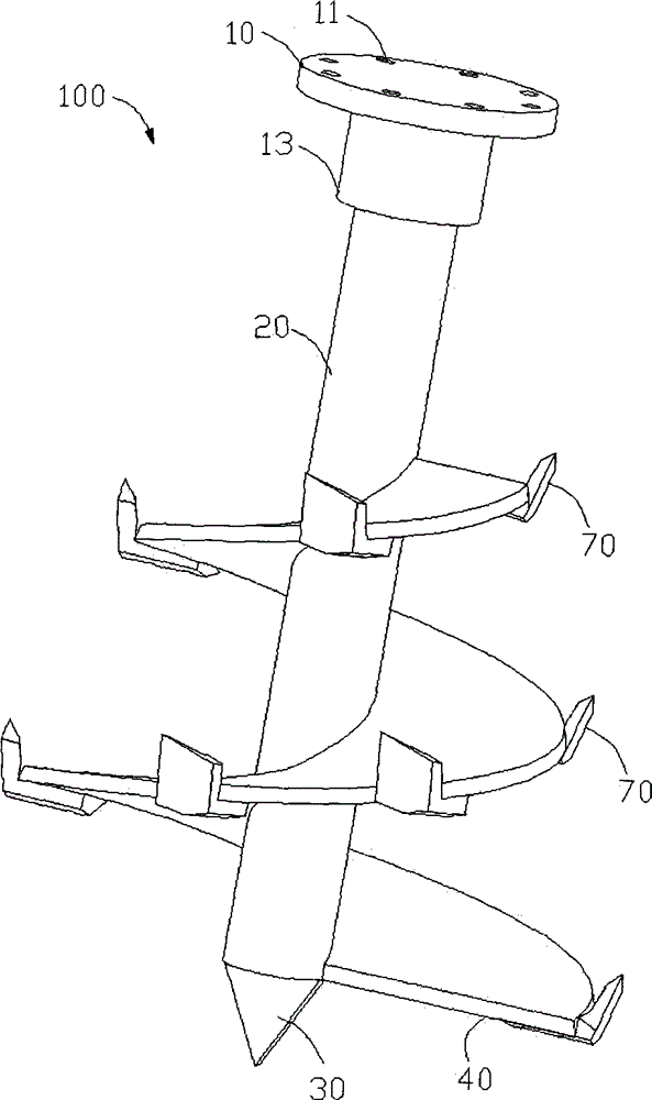
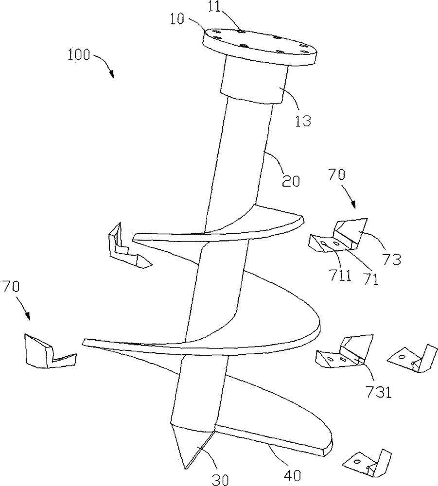
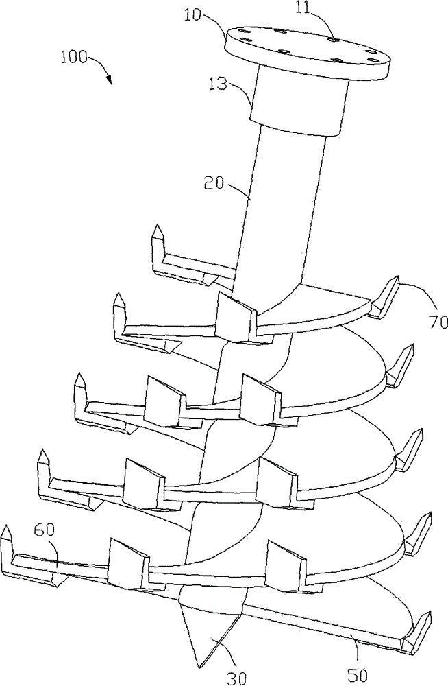
[0022] see figure 1 or image 3 , a tiller drill bit structure 100 includes a connecting flange 10 , a drill rod 20 , a drill bit body 30 , at least one helical blade and a plurality of drill bits 70 . The tiller drill bit structure 100 is used to perform powder ridges on land planted with various crops, such as rice, corn, sugar cane, soybeans, etc. In the first embodiment of the present invention, the tiller bit structure 100 includes a helical blade 40 . In the second embodiment of the present invention, the tiller bit structure 100 includes a left helical blade 50 and a right helical blade 60 .

[0023] The connecting flange 10 defines a plurality of screw holes 11 and extends downwards with a neck 13 for connecting the drill rod 20 . In the embodiment of the present invention, the outer diameter of the neck portion 13 is smaller than the outer diameter of the connecting flange 10 . The connecting flange 10 is locked into the screw hole 11 and the output shaft (not sho...


PUM


Abstract

The invention discloses a subsoiling machine drill structure, which comprises a connecting flange, a drill pipe, a drill body, a plurality of drilling tools and at least one spiral blade, wherein the connecting flange is arranged on one end of the drill pipe; the drill body is arranged on the other end of the drill pipe; the drilling tools are respectively installed on at least one spiral blade; at least one spiral blade is arranged on the periphery of the drill pipe; the diameter of the spiral blade gradually reduces from the drill body to the connecting flange. In the subsoiling machine drill structure disclosed by the invention, at least one spiral blade upwards ridges soil and is cooperated with the drilling tools to cut and rub the soil so as to realize a purpose of soil smashing. In addition, the diameter of at least one spiral blade gradually reduces from the drill body to the connecting flange, i.e. a drilling tool on the lower end of the subsoiling machine drill structure has a high linear speed, and the subsoiling machine drill structure can smash the clumps of special cultivated lands, such as salt and alkali zones and conforms to agricultural requirements.

Description

technical field [0001] The invention relates to an agricultural machine, in particular to a drill bit structure of a tiller. Background technique [0002] The traditional deep plowing and deep loosening process is plowing, beating, and harrowing, which is not only laborious, but also complicated and inefficient. Therefore, for large-area land that needs to be plowed loosely, traditional methods have been unable to adapt. For this reason, many automated plow tillers have appeared. [0003] For example, in the patent document whose application number is 201010270614.3, the application date is 2010.9.3, and the authorization announcement date is 2011.2.16, a rotary milling type powder ridge multifunctional machine is disclosed. There is a linkage rotary abrasion drill device, which is equipped with one or more drill shafts, on which a helical leaf is arranged, and the width of the helical leaf is constant, therefore, the crushing effect of the helical leaf on the surface soil ...

Claims


Application Information

Patent Timeline
Patent Type & Authority Applications(China)
IPC IPC(8): A01B33/06A01B33/10
Inventor 李阳铭
Owner GUANGXI WUFENG MACHINERY CO LTD
Why Eureka
Try Eureka