Raymond mill

A Raymond mill and stand technology, which is applied in grain processing and other directions, can solve the problems of unsuitable production of ultra-fine powder, large powder particle size, energy waste, etc., and achieve less powder falling back and grinding and pulverizing efficiency. High, yield-enhancing effect

Active Publication Date: 2015-06-03
SHANDONG DALIER HEAVY IND CO LTD
View PDF8 Cites 8 Cited by
  • Summary
  • Abstract
  • Description
  • Claims
  • Application Information

AI Technical Summary

Problems solved by technology

[0003] The existing Raymond mill with the above structure mainly has the following defects: First, the shape of the crushing pair (composed of grinding rollers and grinding rings) of the Raymond mill is mostly cylindrical or conical, which is mainly produced by the revolution of the grinding rollers. Centrifugal force squeezes and crushes the material, and the powder produced by it has a large particle size, which is not suitable for the production of ultra-fine powder. The material is carried by the airflow from the crushing area to the classification area. The distance is too long, resulting in some qualified fine powder failing to reach the classification area and then falling back to the crushing area, and being excessively crushed, resulting in waste of energy; and the cylinder is high, so more steel is used, which increases the cost. Big

Method used


Image

  • Raymond mill
  • Raymond mill

Examples


Embodiment Construction

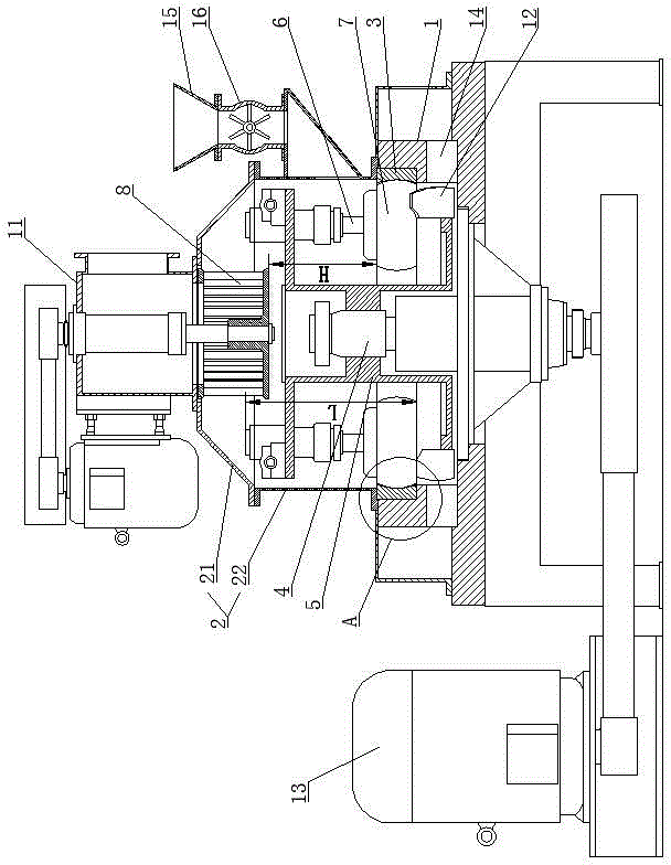
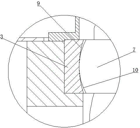
[0015] Such as figure 1 As shown, the Raymond mill includes a machine base 1, a cylinder 2 is connected to the top surface of the machine base 1, a grinding ring 3 is installed in the machine base 1, and a main shaft extending into the cylinder 2 is connected to the machine base 1 for rotation. 4. The main shaft 4 is driven by the main motor 13. The main shaft 4 is connected with a plum blossom frame 5. The top of the plum blossom frame 5 is hinged with multiple sets of grinding roller assemblies. The grinding roller assembly includes a grinding roller hinged on the plum blossom frame 5. The shaft 6 and the grinding roller 7 mounted on the grinding roller shaft 6; the bottom of the plum frame 5 is connected with a plurality of blades 12 for scooping up materials, and the number of blades 12 is the same as that of the grinding roller assembly. The base 1 is provided with an air inlet 14 for air intake into the machine, and the cylinder body 2 is provided with a feeding hopper 1...


PUM


Abstract

The invention discloses a Raymond mill which comprises an engine base, wherein a cylinder is connected to the top surface of the engine base; a grinding ring is arranged in the engine base; a main shaft which stretches into the cylinder is rotationally connected to the engine base; a quincunx rack is connected to the main shaft; multiple sets of grinding roller assemblies are hinged on the quincunx rack; each grinding roller assembly comprises a grinding roller shaft hinged on the quincunx rack and a grinding roller arranged on the grinding roller shaft; a classifier is arranged on the top of the cylinder; a classification roller of the classifier is positioned on the top of an inner cavity of the cylinder; the wall surface contour line of the inner wall surface in the longitudinal section view of the grinding ring is an outwards convex arc; and the side contour line of the outer side in the longitudinal section view of each grinding roller is an outwards convex arc. A product produced by the machine is fine, and the Raymond mill is suitable for production of ultrafine powder.

Description

technical field [0001] The invention relates to a Raymond mill. Background technique [0002] Raymond mill is one of the most widely used equipment for non-metallic mineral processing. The basic structure of the existing Raymond mill is as follows: It includes a machine base, a cylinder is connected to the top surface of the machine base, and a mill is installed in the machine base. The machine base is rotatably connected with a main shaft that extends into the barrel, and the main shaft is connected with a plum blossom frame, and multiple sets of grinding roller assemblies are hinged on the plum blossom frame, and the grinding roller assembly includes grinding rollers hinged on the plum blossom frame The shaft and the grinding roller mounted on the grinding roller shaft, a classifier is installed on the top of the cylinder, and the classifying rotor of the classifier is located on the top of the cylinder cavity. [0003] The existing Raymond mill with the above structure m...

Claims


Application Information

Patent Timeline
Patent Type & Authority Applications(China)
IPC IPC(8): B02C15/08
Inventor 吕勇李文泉
Owner SHANDONG DALIER HEAVY IND CO LTD
Why Eureka
Try Eureka