Electromagnetic joint mechanical hand and patient feeding and control method thereof

A technology of electromagnetic joints and manipulators, applied in the field of flexible manipulators, can solve the problems of hurting patients, unable to fine-tune the grip of paper cups, endangering patients' illness, etc.

Active Publication Date: 2015-06-03
宁波易拓智谱机器人有限公司
View PDF5 Cites 5 Cited by
  • Summary
  • Abstract
  • Description
  • Claims
  • Application Information

AI Technical Summary

Problems solved by technology

The rack-and-pinion flexible arm cannot fine-tune the holding posture of the paper cup
When feeding a patient, the patient's eating posture is not fixed, and subtle changes often occur. If the feeding robot cannot adapt to the slight change in the patient's mouth posture, it may hurt the patient or even endanger the patient's illness.

Method used


Image

  • Electromagnetic joint mechanical hand and patient feeding and control method thereof
  • Electromagnetic joint mechanical hand and patient feeding and control method thereof
  • Electromagnetic joint mechanical hand and patient feeding and control method thereof

Examples


Embodiment 1

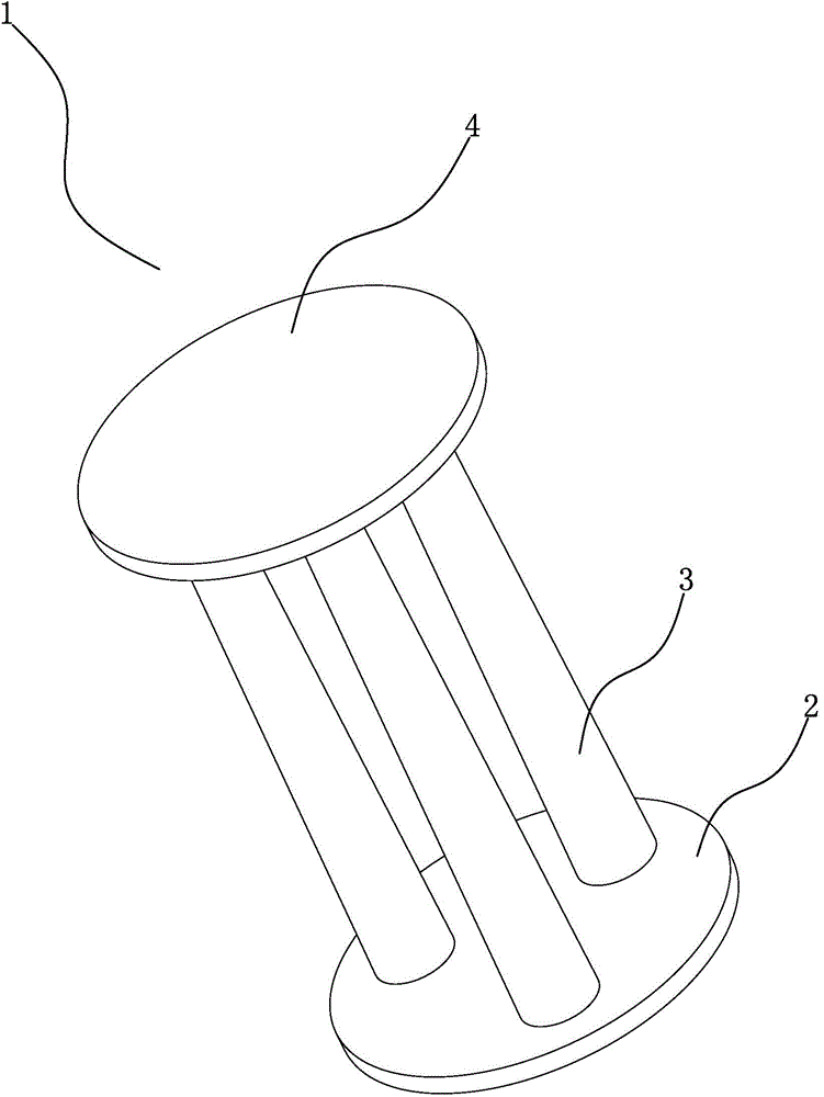
[0037] Such as Figure 1~6 As shown in 11, the electromagnetic joint manipulator of the present invention includes a manipulator palm, a manipulator finger, a manipulator arm, an electromagnetic flexible joint 1 and a circuit control part. One end of the arm is fixed to the frame. see figure 1 , the other end of the arm is connected to the palm through the electromagnetic flexible joint 1 , the palm is connected to the finger through the electromagnetic flexible joint 1 , and each joint of the finger is an electromagnetic flexible joint 1 .

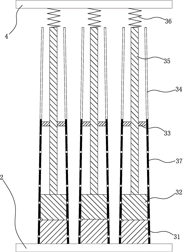
[0038] see figure 1 and figure 2 , the electromagnetic flexible joint 1 includes a lower plate 2, a telescopic column 3 and an upper plate 4, the lower plate 2 is connected with the upper plate 4 through three telescopic columns 3, and the axes of the three telescopic columns 3 are all connected with the upper plate 4 and the lower plate 2 in the circumferential direction The 0°, 120°, and 240° positions are fixed.

[0039] see fi...

Embodiment 2

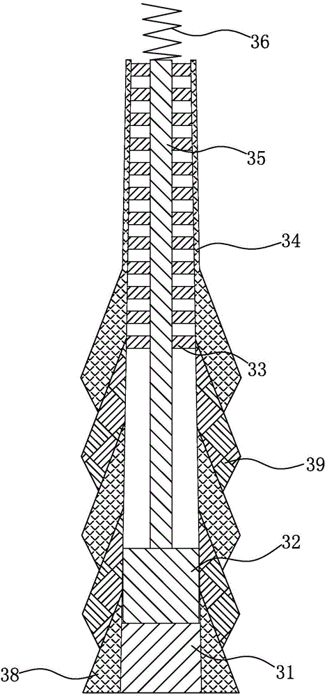
[0056] The difference between this embodiment 2 and embodiment 1 is that, as figure 2 , Figure 7 , Figure 8 , Figure 9 , Figure 10 shown, see figure 2 , The ejector rod 35 is a flexible rod, and the middle part of the inner cavity of the flexible cylinder 34 is provided with a limit ring 33 . The inner diameter of the limit ring 33 is the same as the outer diameter of the push rod 35 , and the limit ring 33 is used to limit the permanent magnet 32 ​​and guide the push rod 35 .

[0057] see Figure 7 , The flexible cylinder 34 is composed of sleeves arranged in the shape of shrimp shells. The sleeve includes a bottom sleeve 38 and a surface limiting sleeve 391 .

[0058] see Figure 8 , The bottom of the flexible cylinder 34 is a bottom cover 38. Bottom cover 38 is circular platform shape, and the peripheral surface of bottom cover 38 external diameters is used to fix lower plate 2, and fixed electromagnet 31 is fixed in bottom cover 38, and a plurality of surfac...


PUM


Abstract

The invention provides an electromagnetic joint mechanical hand, and relates to a flexible mechanical hand, in particular to a mechanical hand used for gripping a paper cup and feeding a patient. The invention aims at providing the electromagnetic joint mechanical hand with the advantages that the structure is simple, the cost is low, the operation is simple and convenient, the adaptation capacity is high, the fine adjustment can be realized according to the size of a gripped object, and the electromagnetic joint mechanical hand can adapt to and compensate the tiny change of the patient posture. The electromagnetic joint mechanical hand comprises an electromagnetic flexible joint (1), wherein the bottom of a flexible tube (34) is fixed with a lower plate (2), an electromagnet (31), a permanent magnet (32) and an ejecting rod (35) are sequentially arranged in an inner cavity of the flexible tube (34) from bottom to top, the electromagnet (31) is fixedly arranged at the bottom of the flexible tube (34), the permanent magnet (32) uses the inner cavity of the flexible tube (34) as a guide rail, the top of the permanent magnet (32) is fixed with the bottom of the ejecting rod (35), and the top of the ejecting rod (35) is connected with an upper plate (4).

Description

technical field [0001] The invention relates to a flexible manipulator, in particular to a manipulator used for grasping paper cups and feeding patients and its grasping, feeding and control methods. Background technique [0002] In the process of gradually replacing people with automated machinery, automated machinery has become a symbol of future technology due to its strong environmental adaptability, tirelessness, and low cost of use. However, complex mechanical mechanisms are prone to many failures, and heavy and large machines cannot perform delicate operations like humans. [0003] In the process of replacing people with automated machines, they have been creating flexible arm joints similar to real people to complete delicate tasks such as catching eggs, paper cups, and even disposable foam plastic lunch boxes and feeding infectious patients. Most of the traditional flexible arms use three sets of rack and pinion to drive the two boards parallel or make them have an...

Claims


Application Information

Patent Timeline
Patent Type & Authority Applications(China)
IPC IPC(8): B25J9/08B25J17/00B25J9/18
CPCB25J9/0009B25J9/08B25J9/12B25J9/1602B25J9/1605B25J9/161B25J9/1671B25J11/009B25J15/0009B25J15/0246B25J17/00B25J17/0241B25J17/0258B25J19/0025
Inventor 李秀荣
Owner 宁波易拓智谱机器人有限公司
Why Eureka
Try Eureka