Patient feeding method of electromagnetic joint mechanical hand

一种电磁关节、机械手的技术,应用在柔性机械手领域,能够解决危害患者生病、伤及患者、纸杯握姿无法进行微调等问题,达到用途广泛、转向灵活的效果

Inactive Publication Date: 2016-08-24
李秀荣
View PDF0 Cites 0 Cited by
  • Summary
  • Abstract
  • Description
  • Claims
  • Application Information

AI Technical Summary

Problems solved by technology

The rack-and-pinion flexible arm cannot fine-tune the holding posture of the paper cup
When feeding a patient, the patient's eating posture is not fixed, and subtle changes often occur. If the feeding robot cannot adapt to the slight change in the patient's mouth posture, it may hurt the patient or even endanger the patient's illness.

Method used


Image

  • Patient feeding method of electromagnetic joint mechanical hand
  • Patient feeding method of electromagnetic joint mechanical hand
  • Patient feeding method of electromagnetic joint mechanical hand

Examples


Embodiment 1

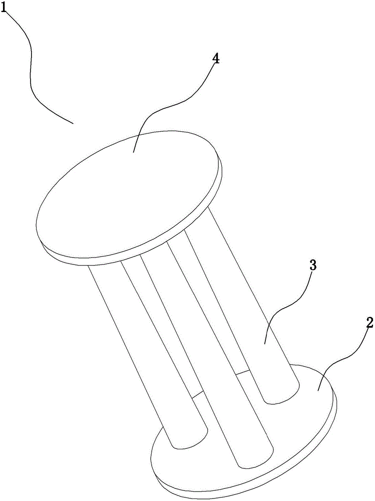
[0049] Such as Figure 1~6 As shown in 11, the electromagnetic joint manipulator of the present invention includes a manipulator palm, a manipulator finger, a manipulator arm, an electromagnetic flexible joint 1 and a circuit control part. One end of the arm is fixed to the frame. see figure 1 , the other end of the arm is connected to the palm through the electromagnetic flexible joint 1 , the palm is connected to the finger through the electromagnetic flexible joint 1 , and each joint of the finger is an electromagnetic flexible joint 1 .

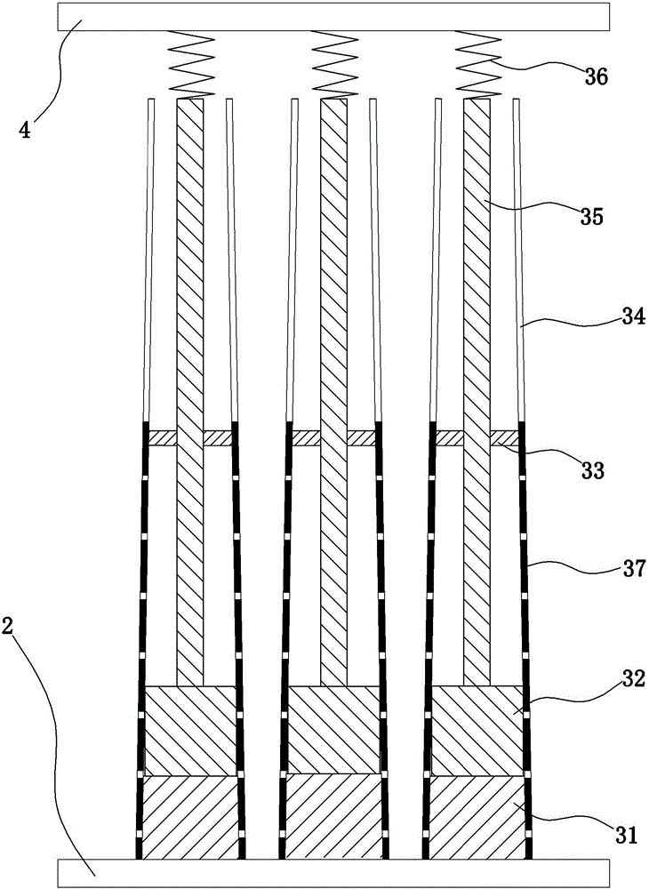
[0050] see figure 1 and figure 2 , the electromagnetic flexible joint 1 includes a lower plate 2, a telescopic column 3 and an upper plate 4, the lower plate 2 is connected with the upper plate 4 through three telescopic columns 3, and the axes of the three telescopic columns 3 are all connected to the circumferential direction of the upper plate 4 and the lower plate 2 0°, 120°, 240° positions are fixed.

[0051] see figure 2 and...

Embodiment 2

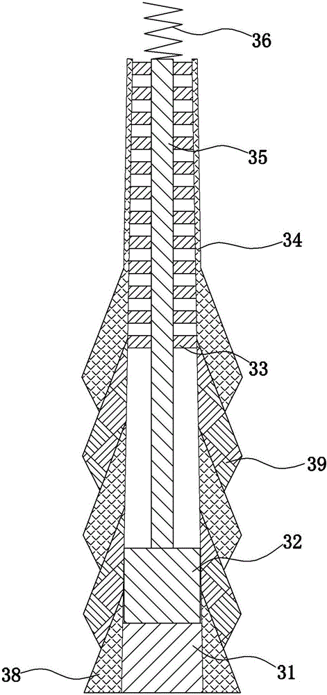
[0068] The difference between this embodiment 2 and embodiment 1 is that, as figure 2 , Figure 7 , Figure 8 , Figure 9 , Figure 10 shown, see figure 2 , The ejector rod 35 is a flexible rod, and the middle part of the inner cavity of the flexible cylinder 34 is provided with a limit ring 33 . The inner diameter of the limit ring 33 is the same as the outer diameter of the push rod 35 , and the limit ring 33 is used to limit the permanent magnet 32 ​​and guide the push rod 35 .

[0069] see Figure 7 , The flexible cylinder 34 is composed of sleeves arranged in the shape of shrimp shells. The sleeve includes a bottom sleeve 38 and a surface limiting sleeve 391 .

[0070] see Figure 8 , The bottom of the flexible cylinder 34 is a bottom cover 38. Bottom cover 38 is circular truncated shape, and the peripheral surface of bottom cover 38 external diameters is used for fixing lower plate 2, and fixed electromagnet 31 is in bottom cover 38, and a plurality of surface...


PUM


Abstract

The invention provides a patient feeding method of an electromagnetic joint mechanical hand, and relates to a flexible mechanical hand, in particular to a mechanical hand used for gripping a paper cup and feeding a patient. The electromagnetic joint mechanical hand provided by the invention is simple in structure, low in cost, simple and convenient to operate and high in adaptive capacity, fine adjustment can be realized according to the size of a gripped object, and the electromagnetic joint mechanical hand can adapt to and compensate for tiny change of the patient posture. The electromagnetic joint mechanical hand provided by the invention comprises an electromagnetic flexible joint (1), wherein the bottom of a flexible tube (34) is fixed with a lower plate (2); an electromagnet (31), a permanent magnet (32) and an ejecting rod (35) are sequentially arranged in the inner chamber of the flexible tube (34) from bottom to top; the electromagnet (31) is fixedly arranged at the bottom of the flexible tube (34); the permanent magnet (32) uses the inner chamber of the flexible tube (34) as a guide rail; the top of the permanent magnet (32) is fixed with the bottom of the ejecting rod (35); the top of the ejecting rod (35) is connected with an upper plate (4).

Description

[0001] The patent application for the present invention is a divisional application. The patent number of the original case is 201510092211.7, and the application date is March 2, 2015. The name of the invention is an electromagnetic joint manipulator and its method of feeding patients and controlling it. technical field [0002] The invention relates to a flexible manipulator, in particular to a manipulator used for grasping paper cups and feeding patients and its grasping, feeding and control methods. Background technique [0003] In the process of gradually replacing people with automated machinery, automated machinery has become a symbol of future technology due to its strong environmental adaptability, tirelessness, and low cost of use. However, complex mechanical mechanisms are prone to many failures, and heavy and large machines cannot perform delicate operations like humans. [0004] In the process of replacing people with automated machines, they have been creating...

Claims


Application Information

Patent Timeline
Patent Type & Authority Applications(China)
IPC IPC(8): B25J9/12B25J17/02B25J19/00B25J11/00
CPCB25J9/0009B25J9/08B25J9/12B25J9/1602B25J9/1605B25J9/161B25J9/1671B25J11/009B25J15/0009B25J15/0246B25J17/00B25J17/0241B25J17/0258B25J19/0025
Inventor 李秀荣
Owner 李秀荣
Why Eureka
Try Eureka