Bottle dividing mechanism of liquid filling machine

A filling machine and bottle separation technology, which is applied in liquid bottling, liquid processing, packaging, etc., can solve the problems of large resource cost and consumption, and achieve the effect of increasing the scope of application and saving connection time.

Inactive Publication Date: 2015-06-03
CHENGDU JIAMEIJIA SCI & TECH
View PDF7 Cites 2 Cited by
  • Summary
  • Abstract
  • Description
  • Claims
  • Application Information

AI Technical Summary

Problems solved by technology

However, when the bottles are on the conveyor belt, they need to be specially arranged so that the subsequent bottle turning mechanism can ensure that each bottle can be filled separately. This arrangement cons

Method used


Image

  • Bottle dividing mechanism of liquid filling machine

Examples


Embodiment Construction

[0009] In order to make the technical problems solved by the present invention, the technical solutions adopted and the beneficial effects produced clearer, the present invention will be further described in detail below in conjunction with the accompanying drawings and embodiments. It should be understood that the specific embodiments described here are only used to explain the present invention, not to limit the present invention.

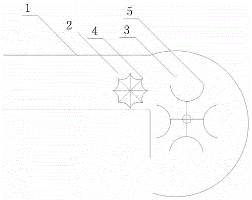
[0010] Specifically, such as figure 1 As shown, the bottle-separating mechanism of a liquid filling machine in this embodiment includes a conveyor belt 1, a star wheel 2 and a bottle rotating part 3, and the star wheel 2 is located at the junction of the conveyor belt 1 and the bottle rotating part 3, and the star wheel 2 can control the frequency and number of bottles entering the bottle rotating part 3. The corresponding ratio between the rotational speed of the star wheel 2 and the rotational speed of the bottle rotating part 3 is determined ...


PUM


Abstract

The invention discloses a bottle dividing mechanism of a liquid filling machine. The bottle dividing mechanism comprises a conveyer belt, a star wheel and a spinner bottle component, wherein the star wheel is arranged at the joint of the conveyer belt and the spinner bottle component; the corresponding ratio of the rotation speed of the star wheel to that of the spinner bottle component is determined according to the gear number of the star wheel and the pushing hand number of the spinner bottle component; the running speed of the conveyer belt is the same as that of the star wheel. According to the technical scheme of the bottle dividing mechanism, the liquid filling machine runs smoothly among bottle feeding, bottle dividing and filling steps, and thus the demanded transition time is saved.

Description

technical field [0001] The invention relates to the field of filling machinery and equipment, in particular to a bottle dividing mechanism of a liquid filling machine. Background technique [0002] The liquid filling machine is used for liquid bottle separation, filling and other operations, all of which are integrated operating structures. Most of the existing liquid filling machines adopt automatic sequential processing, which can directly complete the processes of bottle dividing and filling without manual participation. However, when the bottles are on the conveyor belt, they need to be specially arranged so that the subsequent bottle turning mechanism can ensure that each bottle can be filled separately. This arrangement consumes a lot of resource costs. Even if there is a special bottle-separating mechanism, the separation is done separately for the bottles, and there is no precise cooperation with the subsequent bottle-spinning mechanism. Contents of the invention ...

Claims


Application Information

Patent Timeline
IPC IPC(8): B67C3/24
CPCB67C3/24
Inventor 梁枫
Owner CHENGDU JIAMEIJIA SCI & TECH
Why Eureka
Try Eureka