
Self-refrigerating type cooling device for printing and dyeing work of textile industry

A textile industry and cooling device technology, which is applied in the processing of textile materials, equipment configuration, textiles and papermaking, heating/cooling fabrics, etc., can solve the problems of effect impact, high cooling cost, poor cooling effect, etc., and achieve easy management and extended stay Time, the effect of improving controllability

Inactive Publication Date: 2015-06-03
刘自忠
View PDF0 Cites 0 Cited by
  • Summary
  • Abstract
  • Description
  • Claims
  • Application Information

AI Technical Summary

Problems solved by technology

[0006] The object of the present invention is to provide a self-refrigerating cooling device for printing and dyeing in the textile industry, aiming at the problems of poor cooling effect and high cooling cost of traditional fabric cooling after dyeing, which will affect the effect of fabric printing and dyeing

Method used


Image

  • Self-refrigerating type cooling device for printing and dyeing work of textile industry
  • Self-refrigerating type cooling device for printing and dyeing work of textile industry

Examples


Embodiment Construction

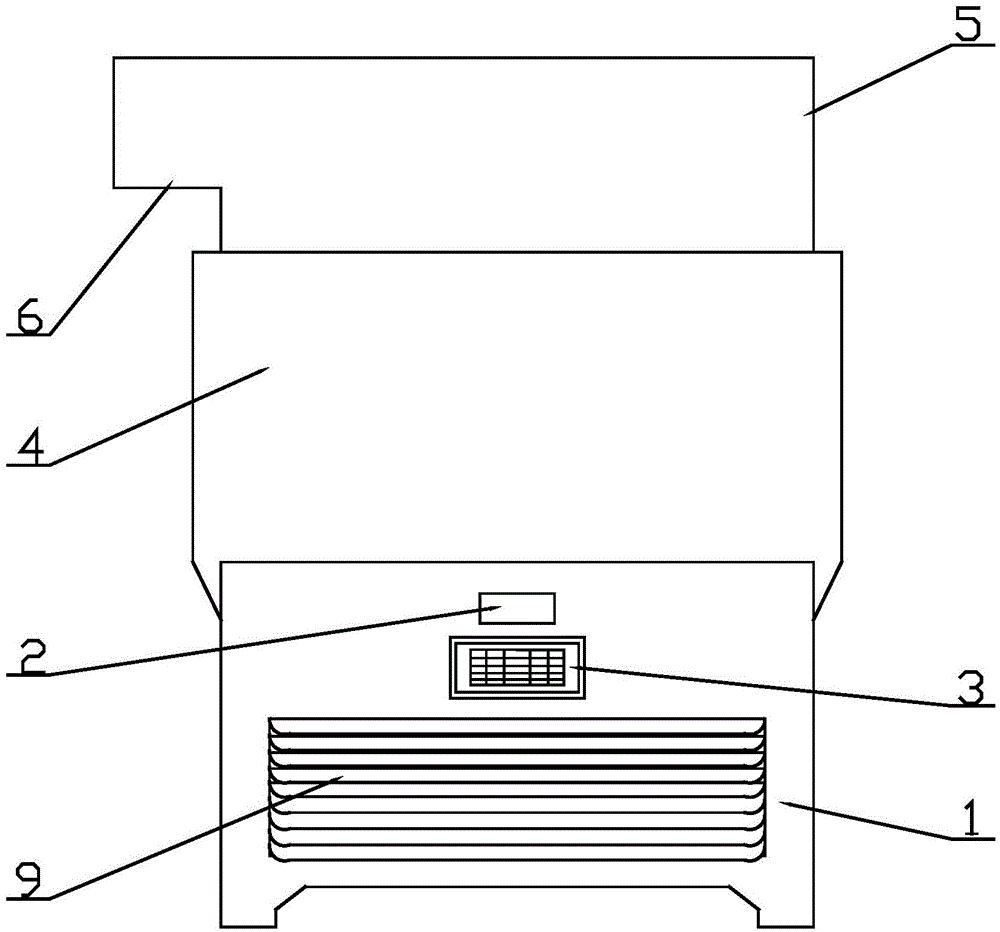
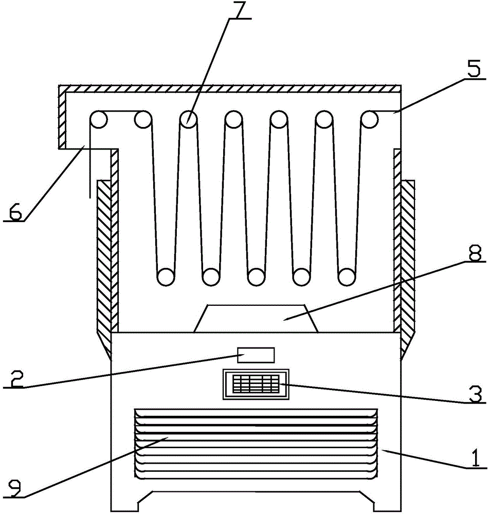
[0016] A self-refrigerated cooling device for printing and dyeing in the textile industry, comprising a refrigeration chamber 1, a thermometer 2, a control panel 3, a working chamber 4, an inlet 5, an outlet 6, a roller set 7, an air-conditioning nozzle 8, and cooling holes 9.

[0017] like figure 1 As shown, the working compartment 4 is arranged on the upper part of the refrigeration compartment 1, and the cooling compartment 1 is provided with cooling holes 9 in the lower part of one side, and a thermometer 2 and a control panel 3 are arranged in the upper part. The refrigeration compartment 1 is specifically a thermoelectric cooling device.

[0018] like figure 2 As shown, the working chamber 4 is provided with an outlet 6 on one side and an inlet 5 on the other side. In the working chamber 4, a roller set 7 is arranged on the upper part, and a cold air nozzle 8 is arranged on the lower part. The cold air One end of the spray head 8 penetrates through the thin wall of th...


PUM


Abstract

The invention discloses a self-refrigerating type cooling device for printing and dyeing work of textile industry, relates to the technical field of printing and dyeing equipment of textile industry and particularly relates to a self- refrigerating type cooling device for printing and dyeing work of textile industry. The self-regenerating type cooling device comprises a refrigerating bin (1), a thermometer (2), a control panel (3), a working bin (4), an inlet (5), an outlet (6), a roller shaft set (7), a cold air spray head (8), a radiating hole (9). The self-refrigerating type cooling device is characterized in that the working bin (4) is arranged on the upper part of the refrigerating bin (1); the radiating hole (9) is formed in the lower part of one side of the refrigerating bin (1); the thermometer (2), the control panel (3) and the working bin (4) are arranged on the upper part of one side of the refrigerating bin (1); the outlet (6) is formed in one side of the working bin (4); the inlet (5) is formed in the other side of the working bin (4); the roller shaft set (7) is arranged on the upper part inside the working bin (4); the cold gas spray head (8) is arranged on the lower part inside the working bin (4).

Description

technical field [0001] The invention relates to the technical field of printing and dyeing equipment in the textile industry, in particular to a self-cooling cooling device for printing and dyeing in the textile industry. Background technique [0002] In the textile printing and dyeing industry, all kinds of open-width fabrics are dyed, printed, coated, shaped and other finishing processes are carried out under high-temperature conditions, and before the fabrics are stacked in open width or rolled, the fabric All need to be fully cooled to prevent dyes, auxiliaries, etc. from being deteriorated due to oxidation-reduction reactions in contact with air at high temperatures. Therefore, the cooling device is an important general-purpose device widely used in the textile printing and dyeing industry. [0003] The current cooling method is to continuously feed tap water or groundwater into one axial end of the hollow large-diameter roller body, and the high-temperature fabric wrap...

Claims


Application Information

Patent Timeline
IPC IPC(8): D06B23/20
CPCD06C7/00
Inventor 刘自忠
Owner 刘自忠
Learn More