Supercharge Your Innovation With Domain-Expert AI Agents!

Phase difference testing circuit

A test circuit and phase difference detection technology, applied in the measurement of electrical variables, the phase angle between voltage and current, and measurement devices, etc., can solve the problem of undercompensation, low sampling accuracy, and no consideration of three-phase unbalance factors of low-voltage loads. and other problems, to achieve the effect of fast response and high detection signal accuracy

Inactive Publication Date: 2015-06-03
XIAN DAYU PHOTOELECTRIC TECH
View PDF0 Cites 6 Cited by
  • Summary
  • Abstract
  • Description
  • Claims
  • Application Information

AI Technical Summary

Problems solved by technology

[0002] Most of the electrical equipment in the low-voltage power distribution system are inductive loads, which cause the current phase to lag behind the voltage phase, and the electric energy is consumed on the transmission line of the power grid, which makes the power supply quality of the power grid deteriorate. Therefore, corresponding compensation measures must be taken, such as switching capacitors to the power grid At present, the main disadvantages of reactive power compensators commonly used in low-voltage power distribution systems are: large volume, low sampling accuracy, and no consideration of low-voltage load three-phase unbalance factors, three-phase Simultaneous switching, the number of switching capacitors is small, the anti-interference ability and reliability are poor, etc., which often cause over-compensation or under-compensation of the power grid.

Method used


Image

  • Phase difference testing circuit
  • Phase difference testing circuit
  • Phase difference testing circuit

Examples


specific Embodiment approach

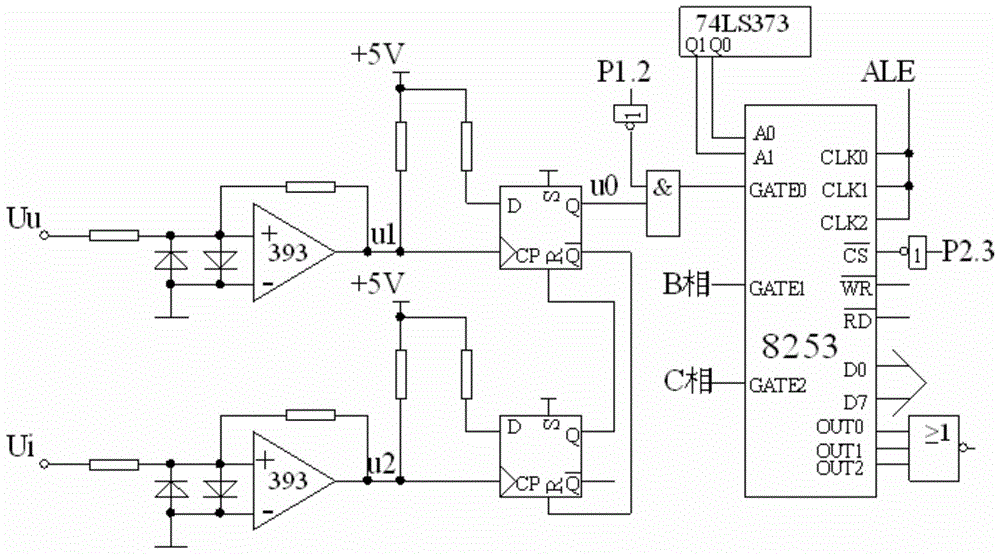
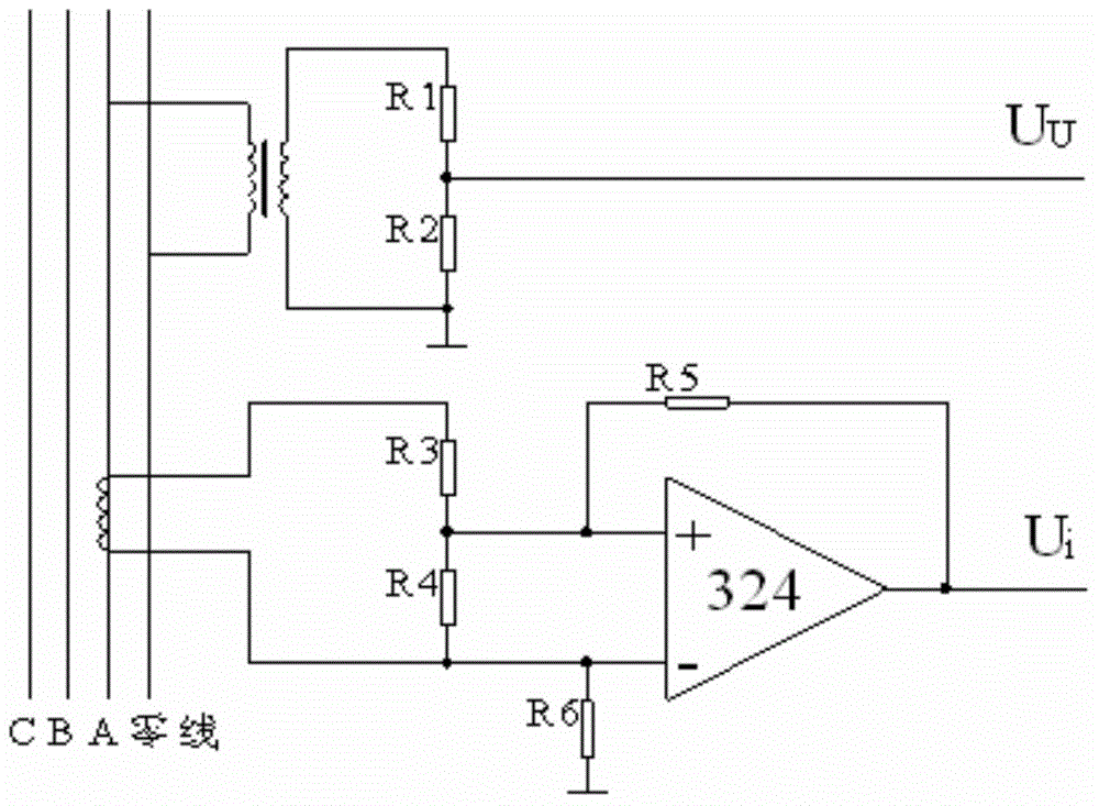
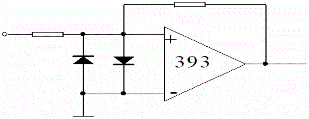
[0016] Such as figure 1 As shown: the phase difference detection circuit of the present invention is mainly composed of phase voltage, phase current input circuit, zero-crossing comparator circuit, voltage comparator circuit, D flip-flop and programmable timer chip 8523, the phase difference detection circuit of the present invention is mainly It is used to detect the phase difference of voltage and current in the power grid for the low-voltage reactive power compensator, and to provide data basis for the power compensator to compensate the power grid. Step down, and convert the current signal into a voltage signal, and then use the voltage comparator to rectify and discriminate the two groups of signals, and the obtained two groups of square wave signals are then passed through the phase detection circuit to obtain the phase difference signal of the two groups of signals. The phase difference signal is input to the chip 8523 for calculation and processing, and the obtained si...


PUM


Abstract

The invention provides a phase difference testing circuit. The phase difference testing circuit is mainly composed of a phase voltage and phase current input circuit, a phase difference detection circuit and a phase difference calculation circuit, wherein the phase voltage and phase current input circuit takes an electromagnetic induction type voltage transformer circuit as a circuit for processing phase voltage and phase current; the phase difference detection circuit is composed of a voltage comparator circuit and a D trigger phase discrimination circuit; the phase difference calculation circuit is a programmable counting device 8253 chip. The phase difference testing circuit provided by the invention has rapid response and high detection signal precision.

Description

technical field [0001] The invention relates to a phase difference test circuit. The invention mainly provides a phase difference test circuit for an intelligent low-voltage reactive power compensator. The invention belongs to the field of low-voltage smart grid control. Background technique [0002] Most of the electrical equipment in the low-voltage power distribution system are inductive loads, which cause the current phase to lag behind the voltage phase, and the electric energy is consumed on the transmission line of the power grid, which reduces the quality of the power supply of the power grid. Therefore, corresponding compensation measures must be taken, such as switching capacitors to the power grid At present, the main disadvantages of reactive power compensators commonly used in low-voltage power distribution systems are: large volume, low sampling accuracy, and no consideration of low-voltage load three-phase unbalance factors, three-phase Simultaneous switching,...

Claims


Application Information

Patent Timeline
Patent Type & Authority Applications(China)
IPC IPC(8): G01R25/00
Inventor 张超
Owner XIAN DAYU PHOTOELECTRIC TECH
Features
  • R&D
  • Intellectual Property
  • Life Sciences
  • Materials
  • Tech Scout
  • Unparalleled Data Quality
  • Higher Quality Content
  • 60% Fewer Hallucinations
Learn More