Microchannel pressure sensor

A technology of pressure sensors and micro-channels, which is applied in the direction of fluid pressure measurement using capacitance changes, etc., can solve the problems of affecting the liquid flow of micro-channels, increasing the manufacturing process, and being susceptible to interference, so as to improve the degree of integration and cost Inexpensive, less distracting effect

Active Publication Date: 2015-09-30
TECHNICAL INST OF PHYSICS & CHEMISTRY - CHINESE ACAD OF SCI
View PDF5 Cites 16 Cited by
  • Summary
  • Abstract
  • Description
  • Claims
  • Application Information

AI Technical Summary

Problems solved by technology

The contact pressure measurement method is to install a pressure sensor at the measured point, and the pressure-sensing element is directly in contact with the measured medium, converts the pressure value into an electrical signal and transmits the signal in a manner suitable for the site, which can be directly and simply felt The pressure changes, but its disadvantages are also obvious: on the one hand, due to the contact between the measuring element and the fluid, the sensor will affect the flow of the fluid, especially for the flow channel at the micro-nano scale. On the other hand, the contact sensor The flow channel will be modified, which will increase the difficulty of the manufacturing process and increase the production cost; the non-contact pressure sensor has a displacement sensor and a capacitive sensor. The amount of deformation can be used to calculate the internal fluid pressure of the pipeline; the non-contact type also has an ultrasonic pressure detection sensor. It propagates in a straight line at a constant speed, and when it propagates from one medium to another, it will produce the principle of reflection and refraction, and then use the probe to receive these reflected and refracted ultrasonic waves to the ultrasonic instrument, which will be enlarged and displayed on the ultrasonic display screen by the ultrasonic instrument , the disadvantage is that the signal at the micro-nano scale is too small, easily disturbed, and the accuracy is too poor
[0003] In short, the existing technology has poor accuracy in detecting the pressure of the microchannel and has technical defects that affect the flow of liquid in the microchannel.

Method used


Image

  • Microchannel pressure sensor
  • Microchannel pressure sensor

Examples


Embodiment 1

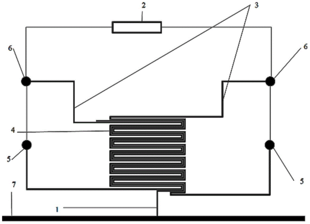
[0023] figure 1 It is a schematic structural diagram of a micro-channel pressure sensor according to a preferred embodiment of the present invention; the micro-channel pressure sensor in this embodiment includes a fluid channel 7, a side-branch micro-channel 1 of the fluid to be measured, and a micro-capacitance signal measurement Circuit 2, the micro-channel detection section 4 of the side-branch micro-channel 1 of the measured fluid, which is far from the fluid flow channel 7, is bent in the shape of "∪, ∩", and two sides of the micro-channel detection section 4 are symmetrically arranged. The liquid micro-electrode flow channel 3 used to form the liquid metal micro-electrode is both connected to the micro-capacitance signal measurement circuit 2 . The liquid micro-electrode channel 3 is located on both sides of the micro-channel detection section 4 to form a micro-capacitor. The length and number of stages of the micro-channel detection section 4 can be designed according ...

Embodiment 2

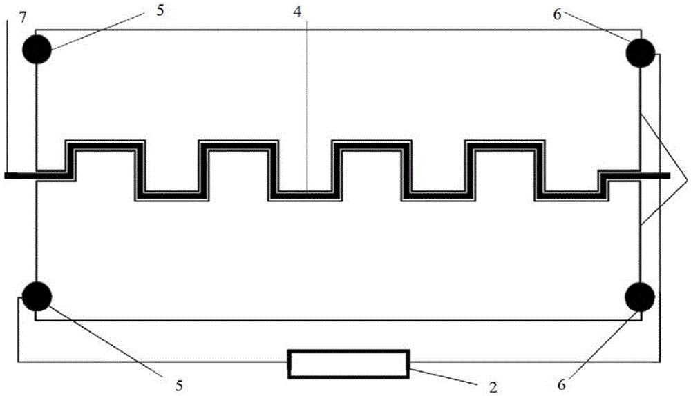
[0029] figure 2 is a schematic structural diagram of a micro-channel pressure sensor according to another preferred embodiment of the present invention; the micro-channel pressure sensor in this embodiment includes a fluid channel 7 and a micro-capacitance signal measurement circuit 2. The fluid channel Two liquid micro-electrode flow channels 3 for forming micro-electrodes are symmetrically arranged on both sides of the micro-channel detection section 4 of 7. The liquid micro-electrode flow channels 3 are parallel to the micro-channel detection section 4 and are used together for constitutes a miniature capacitor. The two liquid micro-electrode flow channels 3 are both connected to the micro-capacitance signal measurement circuit 2 . The micro-channel detection section 4 is bent in the shape of "∪, ∩", and the bending length and series can be designed according to the detection requirements. The liquid micro-electrode flow channel 3 is also bent into a "∪, ∩" shape, and is...


PUM


Abstract

The invention discloses a microchannel pressure sensor which comprises the components of a tested fluid bypass microchannel (1), a micro-capacitance signal measuring system (2) and liquid micro-electrode channels (3). The liquid micro-electrode channels (3) are symmetrically configured at two sides of a micro-channel detecting segment (4) of the tested fluid bypass microchannel (1). Each liquid micro-electrode channel (3) is provided with a liquid micro-electrode inlet (5) and a liquid micro-electrode outlet (6). The two liquid micro-electrode channels (3) are connected with the micro-capacitance signal measuring system (2). According to the microchannel pressure sensor, micro-electrodes are formed at two sides of the micro-channel detecting segment (4). A pressure change in the tested fluid bypass microchannel (1) is obtained through measuring the capacitance, thereby improving measuring accuracy, reducing an interference to liquid flow and furthermore realizing simple manufacture and low cost.

Description

technical field [0001] The invention relates to the technical field of micro-channel pressure detection, and more particularly to a micro-channel pressure sensor. Background technique [0002] Microcapacitive pressure sensor is an important component for detecting microfluidic pressure in microfluidic system, and it is a device for pressure detection in micron-scale or even smaller-scale flow channels. The fluid pressure detection in the flow channel is generally divided into contact type and non-contact type. The main difference between the two is whether the measuring element is in contact with the fluid to be measured. The contact pressure measurement method is to install a pressure sensor at the measured point, and the pressure-sensing element directly contacts the measured medium, converts the pressure value into an electrical signal and transmits the signal in a way that is suitable for the site, which can be directly and simply felt. The pressure changes, but its dis...

Claims


Application Information

Patent Timeline
Patent Type & Authority Applications(China)
IPC IPC(8): G01L9/12
Inventor 桂林牛波高猛
Owner TECHNICAL INST OF PHYSICS & CHEMISTRY - CHINESE ACAD OF SCI
Why Eureka
Try Eureka