
Quick switching device for rear grass discharge of lawn mower

A technology of fast switching and rear grassing, applied to harvesters, agricultural machinery and implements, and other applications, can solve the problem of no two-way selection, etc., and achieve the effects of simple processing, humanized operation, and simple structure

Active Publication Date: 2016-08-24
ZHEJIANG YAT ELECTRICAL APPLIANCE CO LTD
View PDF4 Cites 0 Cited by
  • Summary
  • Abstract
  • Description
  • Claims
  • Application Information

AI Technical Summary

Problems solved by technology

[0002] At present, the rear grass discharge function and no rear discharge function of lawn mowers in the industry are basically single operations, and there is no two-way selection function.

Method used


Image

  • Quick switching device for rear grass discharge of lawn mower
  • Quick switching device for rear grass discharge of lawn mower
  • Quick switching device for rear grass discharge of lawn mower

Examples


Embodiment 1

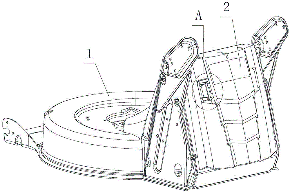
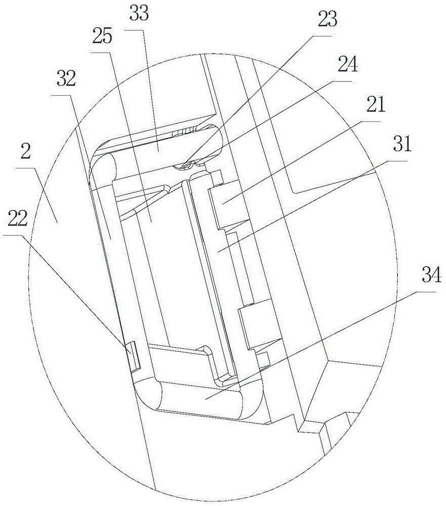
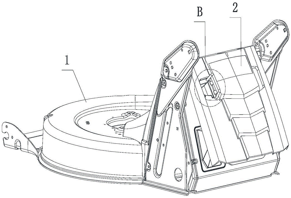
[0028] Such as Figures 1 to 8 Shown is the first embodiment of the fast switching device for grass discharge at the back of the lawn mower, wherein the lawn mower has a casing main body 1, and the casing main body 1 is provided with a grass discharge port 11, and the grass discharge behind the lawn mower The quick switching device includes a back cover 2 and a back cover support, the back cover 2 is covered on the grass outlet 11, the casing main body 1 is provided with an adapter shaft 13, the back cover 2 is provided with a card slot 3 26, and the adapter shaft 13 Clamped in the card slot three 26, the rear cover 2 and the casing main body 1 are rotatably connected through the cooperation of the adapter shaft 13 and the card slot three 26.

[0029] In this embodiment, the back cover support is formed by bending a rod body. After bending, the back cover support forms four parts, which are respectively a transfer part 31, a connecting part 34, a clamping shaft 32 and a suppor...

Embodiment 2

[0032] Such as Figure 9 As shown, the difference from the first embodiment is that the back cover support is an F-shaped structure consisting of only the transfer part 31, the clamping shaft 32 and the support part 33, wherein there are the transfer part 31, the clamping shaft 32 Parallel and perpendicular to the supporting part 33, the supporting part 33 and the transfer part 31 form a T-shaped structure, and the supporting part 33 and the clamping shaft 32 form an L-shaped structure.

Embodiment 3

[0034] Such as Figure 10 As shown, the difference from Embodiment 1 is that the back cover bracket is a T-shaped structure consisting of only the transfer part 31, the clamping shaft 32 and the support part 33, and the clamping shaft 32 and the support part 33 are coaxial, and both It is perpendicular to the transition part 1 31 , at this time, the side where the slot 2 21 is located in the groove 25 is adjacent to the side where the slot 1 22 is located.


PUM


Abstract

The invention provides a rear grass discharging quick switch device for a mower. The mower comprises a housing main body, wherein a grass discharge opening is formed in the housing main body. The rear grass discharging quick switch device comprises a rear cover and a rear cover support, wherein the rear cover is rotationally connected with the housing main body, and covers the grass discharging port; a rotationally connecting part I and a supporting part are arranged on the rear cover support; a rotationally connecting part II is arranged on the rear cover, and rotationally matched with the rotationally connecting part I; a first clamping structure and a second clamping structure are arranged between the rear cover support and the rear cover; when the rotationally connecting part I rotates relative to the rotationally connecting part II, the first clamping structure is released at first, and then the supporting part swings to prop up the rear cover from the housing main body, so as to open the grass discharging port; the rear cover support and the rear cover are in snap fit through the second clamping structure, so as to be fixed with each other. Therefore, the rear discharging function of the mower can be optional when the mower is in operation.

Description

technical field [0001] The invention relates to the field of lawnmowers, in particular to a fast switching device for rear grass discharge of the lawnmower. Background technique [0002] At present, the rear grass discharge function and no rear discharge function of lawn mowers in the industry are basically single operations, and there is no two-way selection function. Contents of the invention [0003] The technical problem to be solved by the present invention is to provide a quick switching device for the rear grass discharge of the lawn mower. Humanize. [0004] In order to solve the above-mentioned existing technical problems, the present invention adopts the following scheme: a fast switching device for grass discharge at the rear of the lawn mower, the lawn mower has a casing main body, the casing main body is provided with a grass discharge port, and the mower The rear grass discharge quick switching device of the grass machine includes a rear cover and a rear co...

Claims


Application Information

Patent Timeline
Patent Type & Authority Patents(China)
IPC IPC(8): A01D57/26
Inventor 梁盛耀周海平卢茂龙
Owner ZHEJIANG YAT ELECTRICAL APPLIANCE CO LTD
Learn More