Gas dust collector

A dust collector and gas technology, applied in the field of dust removal equipment, can solve the problems of unsatisfactory fine dust collection effect, high filter bag replacement cost, high user operation and maintenance cost, and achieves reduction of secondary dust, high practicability, dust removal and purification. Efficiency-enhancing effect

Inactive Publication Date: 2015-06-10
任利萍
View PDF7 Cites 2 Cited by
  • Summary
  • Abstract
  • Description
  • Claims
  • Application Information

AI Technical Summary

Problems solved by technology

[0002] At present, industrial dust is one of the pollution sources of the atmospheric environment. Traditional electrostatic precipitators and bag filters are widely used in the field of gas dust removal, but they have the following deficiencies: 1. Traditional electrostatic precipitators are not ideal for collecting fine dust. If the indoor gas flow rate exceeds the design value, it is easy to cause dust to escape and cause excessive emissions
2. Although the bag filter has good dust collection effect, it has the disadvantages of high filter bag replacement cost and high pressure resistance, resulting in high operation and maintenance costs for users

Method used


Image

  • Gas dust collector
  • Gas dust collector
  • Gas dust collector

Examples


Embodiment 1

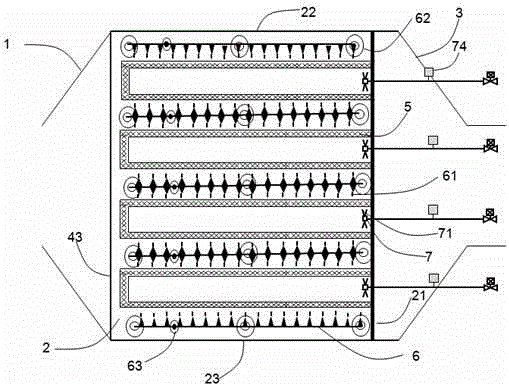
[0039] combine Figure 1 to Figure 3 As shown, the clean air chamber 3 is located above the dust removal chamber 2. It consists of a dust removal chamber 2, a clean air chamber 4, a dust storage box 5, a discharge electrode plate 6, a soot blower 7 and an ash bucket 8. The dust removal chamber 2 is a chamber with a rectangular structure, the front end is connected to the air inlet 1, the bottom support plate 24 is connected to the ash hopper 8, the rear partition 21 is arranged at the rear, the left wallboard 22 is arranged on the left side, and the right side The right side wallboard 23 is set; the clean air chamber 4 is located at the top of the dust removal chamber 2, the bottom of the clean air chamber 4 is connected with the dust removal chamber 2 through the lower partition 41 and forms an independent chamber, and the tail is connected with the air outlet 3. Each dust removal chamber is evenly distributed and fixedly installed with more than 3 dust removal units; The d...

Embodiment 2

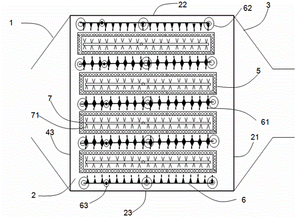
[0044] combine Figure 4 to Figure 6 As shown, its structure is similar to that in Example 1, and includes an air inlet 1, a dust removal chamber 2, an air outlet 3, a clean air chamber 4, a dust accumulation box 5, a discharge electrode plate 6, a soot blower 7 and an ash The bucket 8 is formed; the clean air chamber is still arranged on the top of the dust removal chamber 2, and its specific structure will not be repeated here. The difference is that the dust storage box in the dust removal chamber 2 is connected with the left and right side wall panels of the dust removal chamber. Of course, it can also be connected with the front and rear side wall panels. One side, and be located at the bottom of clean air chamber 4 air outlets. At this time, the sootblower in the dust box moves forward and backward to blow soot.

Embodiment 3

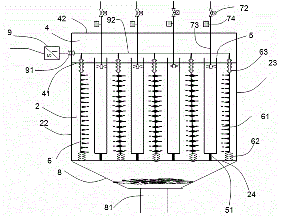
[0046] As a third embodiment, the clean air chamber 4 is arranged adjacent to the side of the dust removal chamber in this embodiment, and the air inlet and outlet of the airflow in this solution are linear. Similarly, the gas dust collector is composed of an air inlet 1, a dust removal chamber 2, an air outlet 3, a dust accumulation box 5, a discharge electrode plate 6, a soot blower 7 and an ash hopper 8; the dust removal unit is composed of a dust accumulation box 5, a discharge electrode plate 6. The dust box support beam 51 and the discharge electrode support insulator 62 are composed; the dust box 5 is hollow and rectangular, and the front end, left and right sides, upper part, and lower part are closed by a metal frame and a high-porosity porous material installed in the frame. The opening is also connected with the rear partition 21 of the dust removal chamber, and the size and shape of the rear partition 21 opening of the dust removal chamber are consistent with the op...


PUM


Abstract

The invention belongs to the field of dedusting equipment and in particular relates to a gas deduster formed by a high-efficiency dust-collecting body and static electricity through combination. The gas deduster is composed of a shell, a discharge electrode plate, a dust collecting box, a soot blower and a dust hopper, wherein the shell is of a rectangular chamber and is divided into an upper independent gas purification chamber and a lower independent dedusting chamber by a partition plate; more than two vent holes are uniformly formed in the partition plate; a gas inlet is formed in the box wall at the front end of the dedusting chamber, and the bottom of the dedusting chamber opens and is provided with a support beam; a gas outlet is formed in the box wall at the rear end of the gas purification chamber; the discharge electrode plate and the dust collecting box are fixedly arranged in the dedusting chamber and are uniformly arranged at intervals; the soot blower is fixedly arranged on the top plate of the dedusting chamber; the dust hopper is fixedly arranged at the bottom of the dedusting chamber. The gas deduster has the beneficial effects of being simple in structure, improving the dedusting efficiency, preventing secondary gas pollution and reducing the maintaining cost.

Description

technical field [0001] The invention relates to a gas dust collector combined with a high-efficiency dust collector and static electricity, belonging to the field of dust removal equipment. Background technique [0002] At present, industrial dust is one of the pollution sources of the atmospheric environment. Traditional electrostatic precipitators and bag filters are widely used in the field of gas dust removal, but they have the following deficiencies: 1. Traditional electrostatic precipitators are not ideal for collecting fine dust. If the indoor gas flow rate exceeds the design value, it is very easy to cause dust to escape and cause excessive emissions. 2. Although the bag filter has good dust collection effect, it has the disadvantages of high filter bag replacement cost and high pressure resistance, resulting in high operation and maintenance costs for users. Contents of the invention [0003] The object of the present invention is to solve the above technical pro...

Claims


Application Information

Patent Timeline
Patent Type & Authority Applications(China)
IPC IPC(8): B03C3/09B03C3/78B03C3/47
Inventor 任利萍
Owner 任利萍
Why Eureka
Try Eureka