Product clamping mechanism

A clamping mechanism and product technology, applied in workpiece clamping devices, manufacturing tools, etc., can solve the problem of not being able to hard contact clamping, and achieve the effect of improving production efficiency, saving manufacturing costs and management costs, and saving labor

Inactive Publication Date: 2015-06-10
BOZHON PRECISION IND TECH CO LTD
View PDF8 Cites 8 Cited by
  • Summary
  • Abstract
  • Description
  • Claims
  • Application Information

AI Technical Summary

Problems solved by technology

[0002] When operating the LED lamp, sometimes it is necessary to clamp the LED lamp. Due to the particularity of the LED lamp, it cannot be clamped by hard contact during the process of clamping the LED lamp. Therefore, it is necessary to design a clamping mechanism with an elastic mechanism to realize Clamping and positioning the product

Method used


Image

  • Product clamping mechanism
  • Product clamping mechanism
  • Product clamping mechanism

Examples


Embodiment Construction

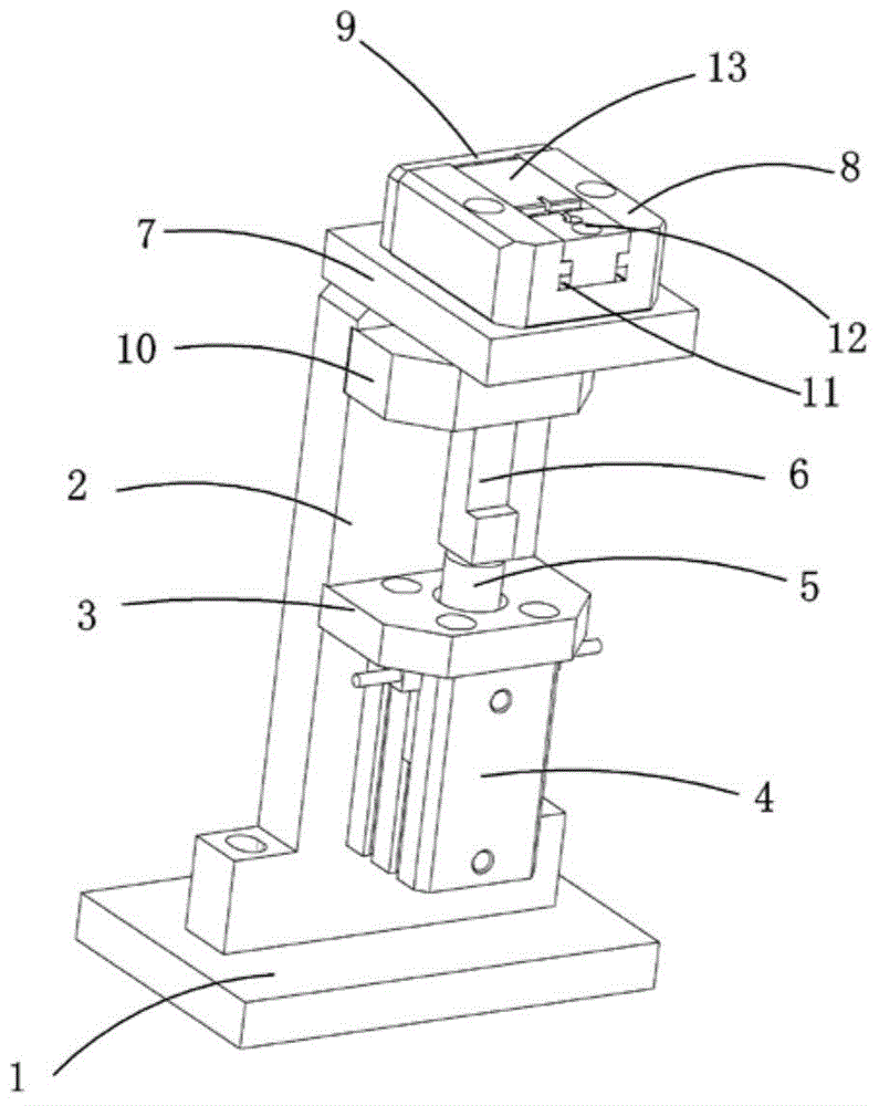
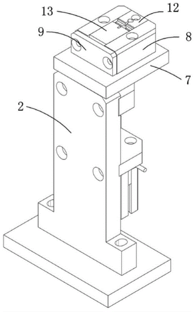
[0018] Examples, see attached Figure 1~4 , a product clamping mechanism, which includes a base 1, a plate 2 is vertically installed on the base, a lifting cylinder fixing plate 3 is fixedly installed in the middle of the supporting plate, and a lifting cylinder fixing plate 3 is installed below the lifting cylinder fixing plate. Cylinder 4, the piston rod 5 of the lifting cylinder passes through the lifting cylinder fixed plate, and the upper end of the piston rod is connected with a lifting slider 6; the driving of the lifting cylinder can drive the lifting slider to move up and down in the vertical direction.

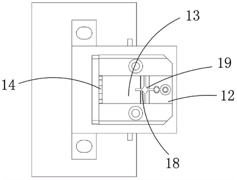
[0019] The upper end of the support plate is equipped with a fixed block 7, the top of the fixed block is screwed and fixedly installed with a fixed seat 8, and the left end of the fixed seat is screwed with a stopper 9, which has a blocking effect; the upper part of the support plate is installed There is a guide plate 10, the guide plate is positioned at the fixed ...


PUM


Abstract

The invention relates to a product clamping mechanism. A supporting plate is arranged on a base of the product clamping mechanism. A lifting cylinder fixing plate is fixedly arranged in the middle of the supporting plate. A lifting cylinder is arranged below the lifting cylinder fixing plate. A piston rod of the lifting cylinder penetrates through the lifting cylinder fixing plate. The upper end of the piston rod is connected with a lifting slide block. A fixing block is arranged at the upper end of the supporting plate. A fixing base is fixedly arranged on the upper portion of the fixing block. The left end of the fixing base is connected with a stop piece. An H-shaped groove is formed in the fixing base. A clamping block is fixed to the right side in the H-shaped groove. A movable block is arranged on the left side in the H-shaped groove in a matched mode. The movable block and the rear stop piece are connected through a spring. An inclined face a is arranged on the lifting slide block. The lower left portion of the movable block is connected with a connection block. An inclined plane b matched with the inclined face a is arranged on the connection block. The lifting cylinder drives the lifting slide block to make the inclined face a on the lifting slide block make contact with the inclined face b, the force, in the vertical and perpendicular direction, of the lifting slide block is converted into force in the horizontal direction, and the movable block moves leftwards and rightwards in the horizontal direction so that a product can be released or clamped.

Description

Technical field: [0001] The invention relates to the field of clamping mechanism equipment, in particular to a clamping mechanism for precisely clamping LED lamps. Background technique: [0002] When operating the LED lamp, sometimes it is necessary to clamp the LED lamp. Due to the particularity of the LED lamp, it cannot be clamped by hard contact during the process of clamping the LED lamp. Therefore, it is necessary to design a clamping mechanism with an elastic mechanism to realize Clamp and position the product. Invention content: [0003] The purpose of the present invention is to provide a product clamping mechanism for the deficiencies of the prior art, which can quickly clamp and position various products with high precision through the power source to push the sliding module, saving time, labor and labor. Improve production efficiency; greatly save manufacturing costs and management costs. [0004] Technical solutions of the present invention are as follows: ...

Claims


Application Information

Patent Timeline
Patent Type & Authority Applications(China)
IPC IPC(8): B25B11/00
CPCB25B11/00
Inventor 吕绍林杨愉强王建福刘陈亮
Owner BOZHON PRECISION IND TECH CO LTD
Why Eureka
Try Eureka