A column-type heliostat installation base and installation method thereof

A technology for installing a base and an installation method, which is applied in basic structural engineering, construction, etc., can solve the problems of easy deformation of wing-shaped components, falling off of wing-shaped components, low installation efficiency, etc., and achieves low construction cost, enhanced stability, and high installation efficiency. Effect

Active Publication Date: 2016-09-28
ZHEJIANG SUPCON SOLAR TECHNOLOGY CO LTD
View PDF9 Cites 0 Cited by
  • Summary
  • Abstract
  • Description
  • Claims
  • Application Information

AI Technical Summary

Problems solved by technology

At present, the installation of some heliostat column bases adopts the method of pre-burying a base on the ground first, and then installing the column on the base, such as a heliostat support device disclosed in Chinese patent 200710179308.7, which involves a heliostat The sun mirror base is independently fixed on the ground. This installation and fixing method requires a solid base to be installed on the ground first, and then the column is installed on it. This column and installation method not only has low installation efficiency and high construction cost, but also Not suitable for uneven ground
[0004] Another way to install the base of the heliostat in the prior art is to weld a wing-shaped component at the bottom of the main body of the column, and then bury the bottom part of the column underground. The wing-shaped component can prevent the base of the heliostat from rotating. function, but the components are welded on the main body of the column. When the column is subjected to external force, the welded wing-shaped components are easily deformed, and even the wing-shaped components will fall off from the main body of the column due to the destruction of the welding structure.

Method used


Image

  • A column-type heliostat installation base and installation method thereof
  • A column-type heliostat installation base and installation method thereof
  • A column-type heliostat installation base and installation method thereof

Examples


Embodiment Construction

[0029] The present invention will be described in detail below in conjunction with the accompanying drawings.

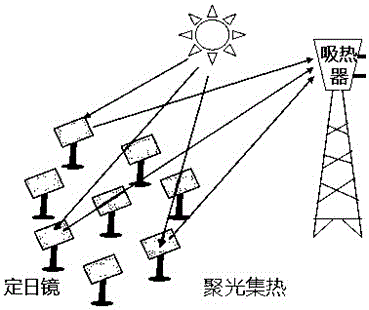
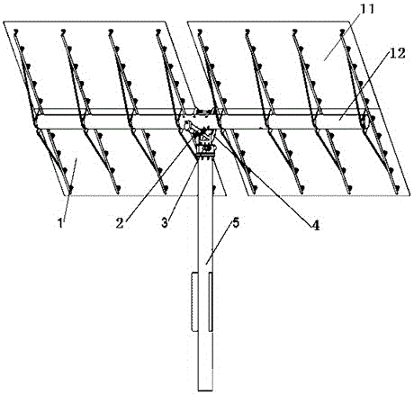
[0030] See figure 1 , tower solar thermal power generation uses a large number of directional mirrors (heliostats) to gather sunlight to a central heat exchanger (heat absorber) installed on the top of the tower, and generates electricity by heating the fluid inside to drive the turbine to rotate , where the heliostat has the function of concentrating light and heat. The overall structure of a typical heliostat see figure 2 , which mainly includes a mirror group 1, an elevation angle driving device 2, an azimuth driving device 3, a connecting seat 4, a column 5, a mirror surface 11, and a mirror group bracket 12, and the mirror group is composed of a plurality of mirror surfaces.

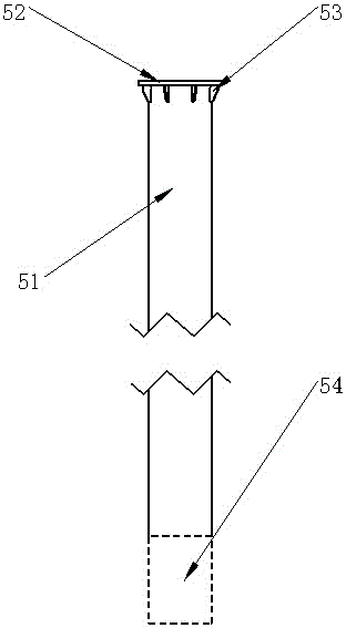
[0031] Aiming at the problems of low installation efficiency, high construction cost, and unsuitability for uneven ground due to the need for pre-embedded bases in the existing heliosta...


PUM


Abstract

The invention relates to a column-type heliostat installation base used for installing the heliostat of a tower-type solar thermal power station, and the invention also relates to an installation method of the base. The column-type heliostat installation base includes a column body and an anti-rotation member located at the lower end of the column body; wherein, the bottom of the column body is designed as an opening; the column-type heliostat installation base is poured on the ground by concrete The pre-dug installation hole is directly fixed and installed in the soil by concrete, and the anti-rotation member prevents the main body of the column from rotating under external load by being firmly combined with the concrete. The column-type heliostat installation base and the installation method thereof of the present invention have high installation efficiency and low construction cost, and are suitable for ground with large unevenness, and the anti-rotation structure arranged on it is firm and durable.

Description

technical field [0001] The invention relates to the field of solar power generation, in particular to the field of tower-type solar thermal power generation, in particular to a heliostat installation base structure and an installation method thereof. Background technique [0002] In the field of energy, solar energy is being used more and more as a clean and renewable energy source. In the field of solar power generation, there are two types of solar power generation: photovoltaic power generation and thermal power generation. With the development of science and technology, especially the rise of computer control technology, solar thermal power generation technology is a new solar energy utilization technology after photovoltaic power generation technology. Solar thermal power generation uses a large number of reflectors to gather the energy of direct sunlight in a focused manner, heat the working fluid, generate high-temperature and high-pressure steam, and use the steam to...

Claims


Application Information

Patent Timeline
Patent Type & Authority Patents(China)
IPC IPC(8): E02D27/32
CPCE02D27/32E02D27/42
Inventor 张旭中江远财陈康立谭潇李心胡中王伊娜
Owner ZHEJIANG SUPCON SOLAR TECHNOLOGY CO LTD
Why Eureka
Try Eureka