
A lift antenna tower and its erection method

A technology for lifting towers and antenna towers, applied in the field of lifting antenna towers and their erection, can solve problems such as difficulties in erecting antenna towers, unsatisfactory erection methods of antenna towers, etc., and achieve the effects of convenient erection operation, simple structure, and low production cost

Active Publication Date: 2017-02-22
贵州振华天通设备有限公司
View PDF5 Cites 0 Cited by
  • Summary
  • Abstract
  • Description
  • Claims
  • Application Information

AI Technical Summary

Problems solved by technology

However, due to geographical constraints (such as steep hillsides, roofs with small usable areas, etc.), it is difficult to erect conventional antenna towers
Therefore the erection mode of existing antenna tower is still not ideal enough

Method used


Image

  • A lift antenna tower and its erection method
  • A lift antenna tower and its erection method
  • A lift antenna tower and its erection method

Examples


Embodiment Construction

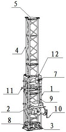
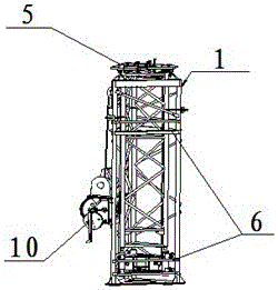
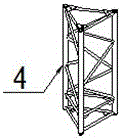
[0017] Embodiments of the present invention: as figure 1 As shown, a hollow lifting tower base 1 is made with conventional section steel (its structure is as follows figure 2 As shown), install existing commercially available electric winch 2 and the conventional transmission mechanism connected with electric winch 2 on the lifting tower base 1, and install lifting pallet 3 in the lifting tower base 1 (its structure is as follows Figure 4 shown), and the lifting pallet 3 is connected with the transmission mechanism, the lifting action of the lifting pallet 3 is controlled by the electric winch 2, and the lifting tower 4 with a multi-stage structure is placed on the lifting pallet 3 (that is, the lifting tower 4 is made into several sections connected structures such as image 3 Shown is the structure of a section of lifting tower), a conventional antenna base 5 is installed on the top of a section of lifting tower 4 at the highest position, and a window 6 that can pass thro...


PUM


Abstract

The invention discloses a lifting antenna tower and an erection method of the lifting antenna tower. When the lifting antenna tower is erected, firstly, fixing a lifting tower base to a foundation on which an antenna needs to be installed, and placing the lifting tower on a hoisting support board through a window of the lifting tower base; then starting an electric winch or a manual winch, and temporarily fixing the lifting tower on the hoisting support board to the lifting tower base through bolts or a pressing plate when the hoisting support board is lifted to the highest position along with the section of the lifting tower; lowering the hoisting support board to the lowest position, placing a next section of the lifting tower on the hoisting support board, lifting the hoisting support board and the section of the lifting tower together by means of the electric winch or the manual winch, connecting the two sections of the lifting tower together by bolts after the top end of the section of the lifting tower is abutted with the bottom end of the previous section of the lifting tower, lifting the hoisting support board to the highest position again by removing the fixing bolts or the pressing plate from the section of the lifting tower, temporarily fixing the section of the lifting tower to the hoisting support board by means of the bolts or the pressing plate, and then performing connection operation of another section of the lifting tower. The lifting antenna tower and the erection method of the lifting antenna tower have the advantages of simple structure, convenience in operation, low production cost and the like.

Description

technical field [0001] The invention relates to a lifting antenna tower and an erection method thereof, belonging to the technical field of antenna erection and assembly. Background technique [0002] Commonly used high-power antennas need to be erected on relatively high antenna towers. The erection of conventional antenna towers requires a large site and requires the assistance of a crane to complete the erection. However, due to geographical constraints (such as steep hillsides, roofs with small usable areas, etc.), it is difficult to erect conventional antenna towers. Therefore the erection mode of existing antenna tower is still not ideal enough. Contents of the invention [0003] The technical problem to be solved by the present invention is to provide a lifting antenna tower and its erection method which occupy a small area, can be erected and dismantled without a crane, and are convenient to erect, so as to overcome the deficiencies of the prior art. [0004] Th...

Claims


Application Information

Patent Timeline
Patent Type & Authority Patents(China)
IPC IPC(8): E04H12/18E04H12/34
Inventor 潘红兵王宝刚王鹰张海彦毛云云郑晓明
Owner 贵州振华天通设备有限公司
Learn More