
Liftable electric fan

An electric fan and lift pipe technology, which is applied to the components of the pumping device for elastic fluids, non-variable-capacity pumps, machines/engines, etc. Fan noise and other problems, to achieve the effect of stable structure, preventing offset and reducing noise

Active Publication Date: 2015-06-10
GREE ELECTRIC APPLIANCES INC
View PDF5 Cites 3 Cited by
  • Summary
  • Abstract
  • Description
  • Claims
  • Application Information

AI Technical Summary

Problems solved by technology

The stability of the lifting tube with this structure is poor, and it is easy to cause the center of gravity to shift during the lifting adjustment process, which will cause the body of the electric fan to shake and increase the noise of the fan

Method used


Image

  • Liftable electric fan
  • Liftable electric fan
  • Liftable electric fan

Examples


Embodiment Construction

[0024] The present invention will be described in detail below in conjunction with embodiments. It should be noted that the embodiments in the application and the features in the embodiments can be combined with each other if there is no conflict.

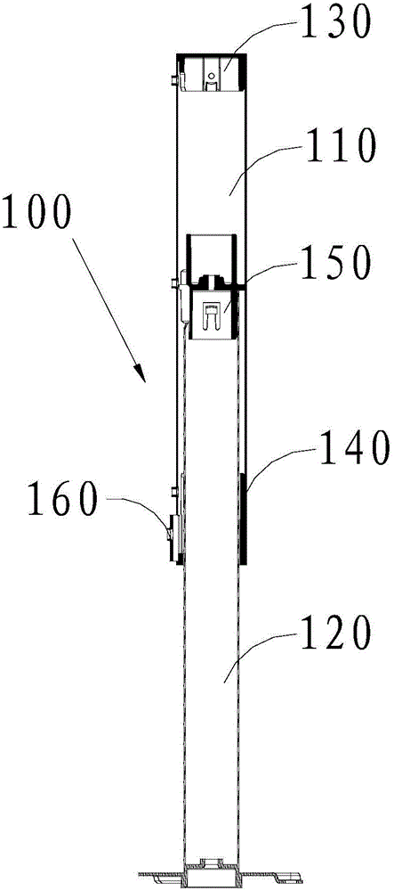
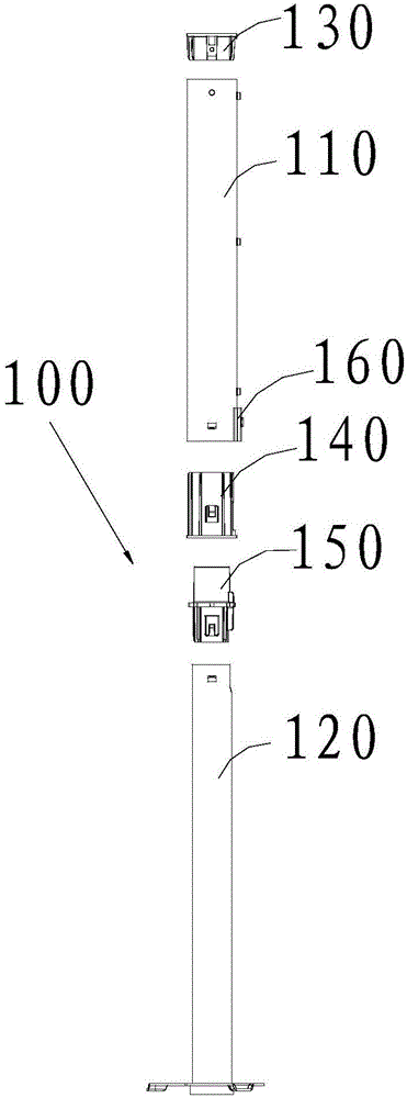
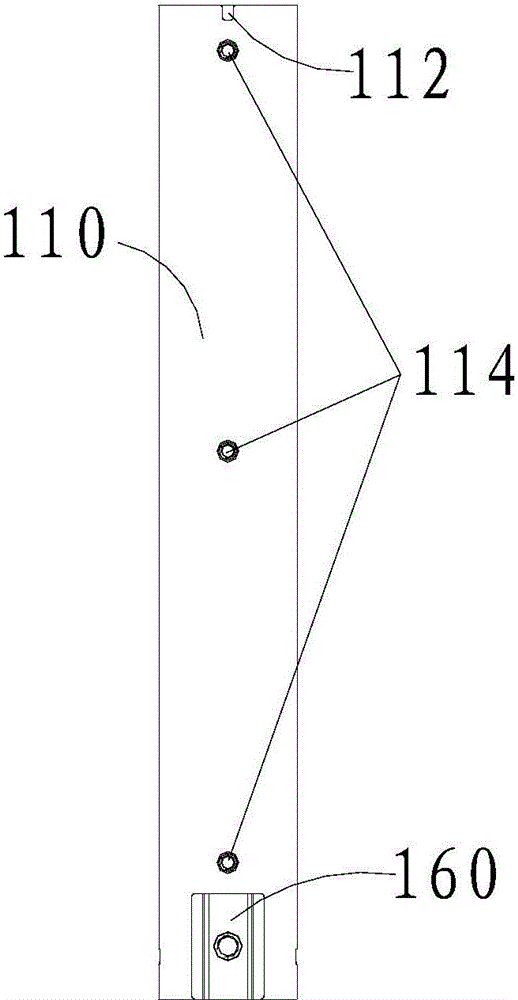
[0025] See Figure 1 to Figure 6 The present invention provides a liftable electric fan, which includes a lift tube 100 and a body 200. The lifting pipe 100 is used to adjust the height of the electric fan, and includes an upper pipe 110 and a lower pipe 120; wherein, the upper pipe 110 is fixedly installed inside the fuselage 200, the inner diameter of the upper pipe 110 is larger than the outer diameter of the lower pipe 120, and the lower pipe 120 One end of the tube is sleeved in the upper tube 110, and the lower tube 120 can telescope in the upper tube 110.

[0026] In addition, the lifting pipe 100 of the present invention is also provided with a locking device 160, such as figure 1 with figure 2 As shown, the locking device 16...


PUM


Abstract

The invention discloses a liftable electric fan which comprises a body and a lifting tube, wherein the lifting tube comprises an upper tube and a lower tube; the upper tube is fixedly mounted in the body; the inner diameter of the upper tube is greater than the outer diameter of the lower tube; one end of the lower tube is sleeved by the upper tube; the lower tube can extend and retract in the upper tube. The liftable electric fan disclosed by the invention adopts the lifting tube structure which is thick on the upper part and thin on the lower part, and moreover, the relatively thick upper tube is mounted in the body, so that the structural compactness is increased; the upper tube plays a reinforcing role on the body, so that the integral structure is relatively steady, the center of gravity is relatively centralized, and the height can be adjusted by extending and retracting the lower tube during use. Therefore, the center of gravity in the adjusting process is effectively prevented from being deviated, and noise caused by shake of the body is reduced.

Description

Technical field [0001] The present invention relates to the technical field of household appliances, in particular to a liftable electric fan. Background technique [0002] At present, most of the liftable electric fans on the market are adjusted in height through a lift tube. The lifting pipe includes an upper pipe with a thinner diameter and a thicker lower pipe. One end of the upper pipe is connected with the machine body, and the other end is sleeved in the lower pipe. The purpose of lifting adjustment is achieved by the expansion and contraction of the upper pipe in the lower pipe. The lifting pipe of this structure has poor stability and easily causes the center of gravity to shift during the lifting adjustment process, which causes the body of the electric fan to shake and increase the noise of the fan. Summary of the invention [0003] The invention provides a liftable electric fan with good structural stability. [0004] To achieve the above objective, the present inventi...

Claims


Application Information

Patent Timeline
Patent Type & Authority Applications(China)
IPC IPC(8): F04D29/00
CPCF04D29/002
Inventor 刘瑶黄礼华李曙光陈宇强严必照
Owner GREE ELECTRIC APPLIANCES INC
Learn More