Pressure-limiting valve

A pressure limiting valve and pressure relief technology, applied in the field of pressure limiting valves, can solve the problems of small outflow openings and easy clogging, and achieve the effect of preventing clogging and good distribution

Inactive Publication Date: 2015-06-10
LIEBHERR MACHINES BULLE
View PDF6 Cites 5 Cited by
  • Summary
  • Abstract
  • Description
  • Claims
  • Application Information

AI Technical Summary

Problems solved by technology

However, the outflow opening is only allowed to have a very small cross-section and is therefore easily clogged

Method used


Image

  • Pressure-limiting valve
  • Pressure-limiting valve
  • Pressure-limiting valve

Examples


Embodiment Construction

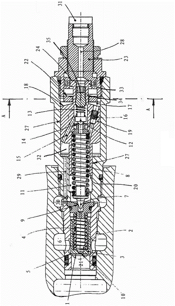
[0042] In the following it will now first be described in detail in the Figures 1 to 4 The basic function of the pressure limiting valve shown in .

[0043] The pressure limiting valve here has a main stage with a main piston 3 , which prevents or releases the connection between the pressure connection 21 and the tank connection 6 . The main piston 3 is pretensioned via a compression spring 4 against the pressure from the pressure port 21 acting on the end side 1 of the main piston. The edge 5 of the main piston 3 cooperates with the corresponding valve seat here and thus in the presence of the main piston. figure 1 In the position shown in , the passage between the pressure connection 21 and the tank connection 6 is blocked.

[0044] The main piston 3 is arranged in the main piston cavity of the housing in an axially movable manner. Here, the main piston chamber is connected to the pressure port 21 via the intermediate wall 10 on the front side of the main piston 3 . The...


PUM


Abstract

The invention relates to a pressure-limiting valve with a master grade and a pre-control grade. The pre-control grade is used for controlling opening movement of the master grade. The pre-control grade has spring elements (8), pre-tightening forces of which are used for determining opening pressure of the pressure-limiting valve. The spring elements are supported on a guide piston (19). The guide piston can be movably arranged in a housing of the pressure-limiting valve and is provided with a guide chamber (17) at the rear portion. The guide chamber is sized depending on the position of the guide piston. A control fluid of the pre-control grade flows into the guide chamber at the rear portion such that pre-tightening forces of the spring elements (8) increased by movement of the guide piston after the pre-control grade is opened. A pressure-relief grade is arranged and used for limiting pressure of the pre-control grade and provided with a valve element (12) pre-tensioned to reverse to a valve seat (14). Hence, at least one outflow opening (26) can be arranged between the valve element and the valve seat when the valve element and / or the valve seat are formed for closing the pressure-relief grade. The fluid can flow out of the outflow opening from the pre-control grade.

Description

technical field [0001] The invention relates to a pressure limiting valve with a main stage and a pilot stage, which controls the opening movement of the main stage, wherein the pilot stage has a spring element, the pretension of which determines the pressure limiting valve Turn on the pressure. Background technique [0002] Such a two-stage pressure limiting valve is known, for example, from US Pat. No. 6,039,070 A in which a spring element is supported on a pilot piston which is displaceably arranged in the housing of the pressure limiting valve. After opening of the pilot stage, the control fluid flow first flows into the front pilot chamber and from there continues via the control opening into the rear pilot chamber arranged downstream of the pilot piston. By filling the rear pilot chamber, the pilot piston moves against the spring element, so that the pretension of the spring element and thus the opening pressure of the pilot valve increases. Pressure peaks are avoide...

Claims


Application Information

Patent Timeline
Patent Type & Authority Applications(China)
IPC IPC(8): F16K17/20
CPCF16K17/105F16K17/24F16K31/36
Inventor 帕斯卡尔·普罗金
Owner LIEBHERR MACHINES BULLE
Why Eureka
Try Eureka