Fast pipe joint insertion structure

A pipe joint and joint body technology, which is applied in mechanical equipment, couplings, etc., can solve the problems of easily affecting the sealing effect of the sealing ring, expanding the hole diameter of the sealing ring, and difficult to control the size.

Inactive Publication Date: 2015-06-10
浙江超润润滑元件有限公司
View PDF5 Cites 13 Cited by
  • Summary
  • Abstract
  • Description
  • Claims
  • Application Information

AI Technical Summary

Problems solved by technology

[0006] The invention solves the problem that the existing pipe joints are connected by threads, which requires the assistance of other tools to complete, and there is a defect of low efficiency. fast and efficient
[0007] The present invention also solves the defects that the existing pipe joints are connected by sealing rings, and the tool is directly inserted into the hole to process the sealing ring groove, the size is not easy to control, and the sealing effect of the sealing rings is easily affected. The tool processes the sealing ring hole with openings on bot...

Method used


Image

  • Fast pipe joint insertion structure
  • Fast pipe joint insertion structure
  • Fast pipe joint insertion structure

Examples


Embodiment

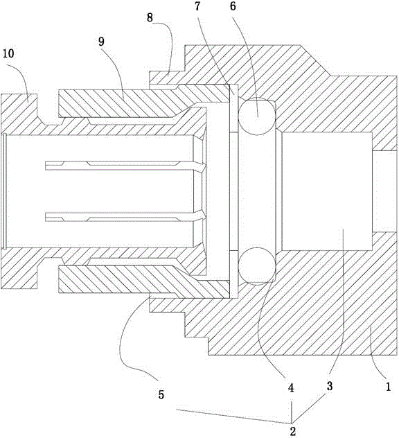
[0026] Embodiment: A kind of quick-plug structure of pipe joint (see attached figure 1 ), including a joint body 1, the joint body is provided with an inner hole 2 through which a pipe is inserted, and the inner hole is stepped. The inner hole includes a liquid hole, a channel hole 3 , an open sealing ring hole 4 and a plug hole 5 which are distributed in sequence. The diameter of the liquid hole is the smallest, followed by the diameter of the passage hole, the diameter of the open sealing ring hole is greater than the diameter of the passage hole, the diameter of the plug hole is the largest, and the diameter of the passage hole is equal to the outer diameter of the pipe. The joint body is a necking part 8 at one end of the plug hole.

[0027] A sealing ring 6 is placed in the open sealing ring hole, and the side of the open sealing ring hole facing the plug hole is an open structure, and a metal gasket 7 is placed at the inner end of the plug hole, and the metal gasket clo...

Embodiment 2

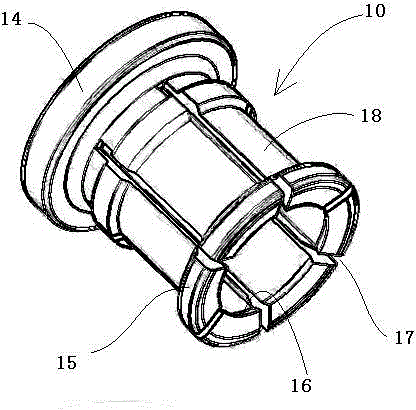
[0030] Embodiment 2: A pipe joint quick-plug structure, the inner wall of the claw of the buckle is an inclined structure, and the diameter of the inner wall at the end of the claw is smaller than the diameter of the inner wall at the root of the claw, so that the inner wall of the claw has a larger inclination Angle, when the claws buckle the outer wall of the pipe, it will not cause bite marks on the outer wall of the pipe. In order to increase the anti-off ability of the pipe, printing can be added on the inner wall of the claw to increase the friction with the outer wall of the pipe. Refer to Example 1 for all the other structures.


PUM


Abstract

The invention relates to a fast pipe joint insertion structure. According to the fast pipe joint insertion structure, the defect of low efficiency caused by the fact that conventional pipe joint connection adopts a threaded manner and can be completed through assistance and matching of other tools. The fast pipe joint insertion structure comprises a joint body, wherein inner holes allowing a pipe to penetrate through are formed in the joint body and comprise a liquid hole, an access hole, an open type seal ring hole and a plug hole; a plug is arranged in the plug hole; the end part of the plug closes the open type seal ring hole to form a seal ring slot hole; a seal ring is arranged in the seal ring slot hole; a buckle for buckling the pipe is arranged in the plug; the outer wall of the buckle and the inner wall of the plug form a retaining structure. The seal ring, the plug and the buckle are sequentially placed in the inner holes, the pipe penetrates through the buckle, the plug and the seal ring from outside and extends to the end of the access hole, the buckle buckles the outer surface of the pipe, the pipe connection adopts an insertion manner, other auxiliary tools are not required, a wrench for threaded screwing is not required, and the efficiency is high; the seal ring is mounted in the open type seal ring hole, the processing is convenient, and the seal ring is convenient to mount.

Description

technical field [0001] The invention relates to a pipe joint connection structure, in particular to a pipe joint quick-insert structure used to connect oil inlet and outlet ports of various components of a lubrication system. Background technique [0002] The pipe joint is a connection tool between pipes and a detachable connection point between components and pipes. It plays an indispensable and important role in pipe fittings, and it is one of the two main components of hydraulic pipelines. [0003] There are many types of pipe joints. Commonly used pipe joints can generally be divided into two types: hard pipe joints and hose joints. If it is divided according to the connection method of the pipe joint and the pipe, the hard pipe joint has three types: flare type, ferrule type and welding type, and the hose joint is mainly a buckle type hose joint. [0004] The connection between the pipe and the pipe joint is mainly through threaded connection, so other tools are requi...

Claims


Application Information

Patent Timeline
IPC IPC(8): F16L37/091
CPCF16L37/091
Inventor 项胜华
Owner 浙江超润润滑元件有限公司
Why Eureka
Try Eureka