High dynamic range imaging method of camera array

A high dynamic range, camera array technology, applied in image communication, selective content distribution, electrical components, etc., can solve problems such as low dynamic range, ghosting, and long time-consuming multiple exposure techniques, and achieve long-term solutions.

Active Publication Date: 2015-06-10
XIAN ANMENG INTELLIGENT TECH CO LTD
View PDF6 Cites 16 Cited by
  • Summary
  • Abstract
  • Description
  • Claims
  • Application Information

AI Technical Summary

Problems solved by technology

[0004] In order to overcome the deficiency of the low dynamic range of the existing camera array imaging method, the present invention provides a camera array high dynamic range imagin

Method used


Image

  • High dynamic range imaging method of camera array
  • High dynamic range imaging method of camera array
  • High dynamic range imaging method of camera array

Examples


Embodiment Construction

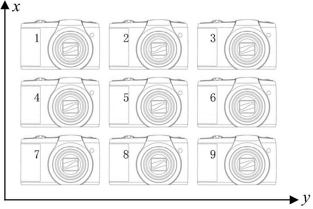
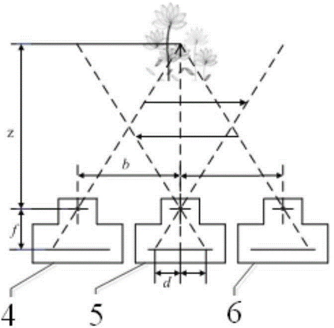
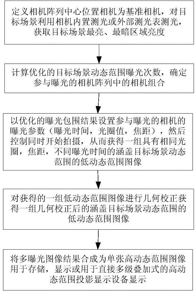
[0024] refer to Figure 1-3 . The present invention is described in detail by taking 9 cameras forming a 3*3 camera array as an example. The camera array high dynamic range imaging method of the present invention specifically includes the following steps:

[0025] 1. Fix 9 cameras with brackets in three rows and three columns to form a parallel camera array. When fixed, the cameras in the horizontal direction are on the same horizontal line, and the cameras in the vertical direction are on the same vertical line. The cameras should be at a minimum equal distance between each other in the horizontal and vertical directions, and the main axes of the lenses of the N cameras should be parallel. The 9 cameras are numbered sequentially, namely camera No. 1, camera No. 2, camera No. 3, camera No. 4, camera No. 5, camera No. 6, camera No. 7, camera No. 8, camera No. 9 No. Camera 9. Define the camera at the center of the camera array as the reference camera, that is, camera No. 5 5...


PUM


Abstract

The invention discloses a high dynamic range imaging method of a camera array, and aims at solving the technical problem of low dynamic range of the existing camera array imaging method. According to the technical scheme, the method is that the maximum brightness and the minimum brightness of a target scene are obtained through a light meter or a built-in light detector in the camera so as to gain a group of optimized exposure bracketing grades; the camera combination participating in exposure in the array is determined, and the camera scene is synchronously shot through the camera combination so as to obtain a group of low dynamic range image containing different exposure settings of the target scene; the group of low dynamic range images is geometrically corrected according to the geometric relationship between the camera layout and the target scene to obtain a group of corrected low dynamic range images which cover the target scene dynamic range. According to the method, the total exposure time, of using the multi-exposure technology to obtain the high dynamic range image, which is equal to the sum of the times of a plurality of exposure, is reduced to the longest exposure time of the exposure bracketing combination; the problems of large time consumption due to exposing the static scene high dynamic range at a plurality of times and ghosting of imaging of the dynamic scene high dynamic range can be solved.

Description

technical field [0001] The invention relates to the field of digital imaging, in particular to a camera array high dynamic range imaging method. Background technique [0002] The imaging resolution and dynamic range of digital imaging equipment are two main indicators to measure the imaging quality of imaging equipment. The imaging resolution of digital imaging equipment has been developed rapidly in recent decades, but the improvement of dynamic range has been very small. As a result, it is difficult to capture imaging details in scenes with backlighting or large changes in light. [0003] The dynamic range of single-exposure imaging of current digital imaging equipment is much lower than the visible dynamic range of human vision (including professional-grade SLR cameras, professional monitoring equipment, personal handheld terminals, etc.). Due to the limited dynamic range of images that can be obtained with a single exposure, it is called a low dynamic range imaging devi...

Claims


Application Information

Patent Timeline
IPC IPC(8): H04N21/235H04N21/232
Inventor 白本督刘颖范九伦
Owner XIAN ANMENG INTELLIGENT TECH CO LTD
Why Eureka
Try Eureka