In-pixel high dynamic range imaging system and imaging sensor pixels

An imaging sensor and pixel technology, applied in radiation control devices, diodes, transistors, etc., can solve the problems of reducing dynamic range and signal-to-noise ratio

Active Publication Date: 2012-12-12
OMNIVISION TECH INC
View PDF8 Cites 34 Cited by
  • Summary
  • Abstract
  • Description
  • Claims
  • Application Information

AI Technical Summary

Problems solved by technology

This will lead to saturation of the floating diffusion node, resulting in reduced dynamic range and reduced signal-to-noise ratio (SNR)

Method used


Image

  • In-pixel high dynamic range imaging system and imaging sensor pixels
  • In-pixel high dynamic range imaging system and imaging sensor pixels
  • In-pixel high dynamic range imaging system and imaging sensor pixels

Examples


Embodiment Construction

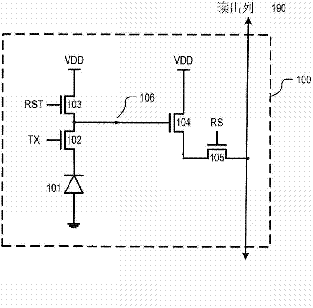
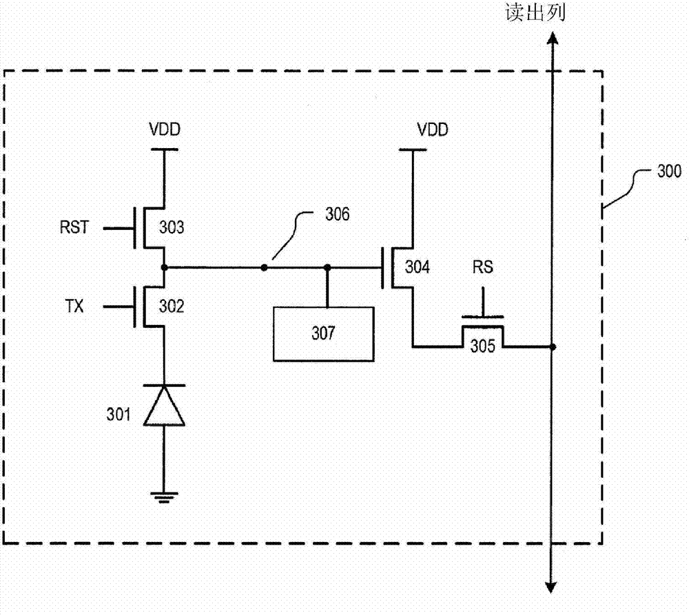
[0020] Embodiments of the present invention describe providing high dynamic range imaging (HDRI or just HDR) to imaging pixels by coupling their floating diffusion nodes to multiple metal oxide semiconductor (MOS) capacitive regions. It should be understood that the MOS capacitive region "turns on" (i.e., changes the voltage of the floating diffusion node) only when the voltage at the floating diffusion node (or the voltage difference between the gate node and the floating diffusion node) is greater than the threshold voltage of the MOS capacitive region. total capacitance); until the MOS capacitance region is "on", it has no effect on the total capacitance or conversion gain of the imaging pixel.

[0021] Each of the multiple MOS capacitive regions utilized by embodiments of the present invention may have a different threshold voltage, thereby "turning on" under different lighting conditions. This increases the dynamic range of the imaging pixels, thereby providing HDR for th...


PUM


Abstract

The application relates to an in-pixel high dynamic range imaging system and imaging sensor pixels. Embodiments of the invention describe providing high dynamic range imaging (HDRI or simply HDR) to an imaging pixel by coupling a floating diffusion node of the imaging pixel to a plurality of metal-oxide semiconductor (MOS) capacitance regions. It is understood that a MOS capacitance region only turns on (i.e., changes the overall capacitance of the floating diffusion node) when the voltage at the floating diffusion node (or a voltage difference between a gate node and the floating diffusion node) is greater than its threshold voltage; before the MOS capacitance region is on it does not contribute to the overall capacitance or conversion gain of the floating diffusion node. Each of the MOS capacitance regions will have different threshold voltages, thereby turning on at different illumination conditions. This increases the dynamic range of the imaging pixel, thereby providing HDR for the host imaging system.

Description

technical field [0001] Embodiments of the invention relate generally to image capture devices, and more particularly, but not exclusively, to enhancing the dynamic range of image capture devices. Background technique [0002] The image capture device includes an image sensor and an imaging lens. The imaging lens focuses light onto the image sensor to form an image, and the image sensor converts the light into an electrical signal. Electrical signals are output from the image capture device to other components of the main electronic system. The electronic system may be, for example, a mobile phone, computer, digital camera, or medical device. [0003] As the pixel unit becomes smaller, it becomes more difficult for the pixel unit to output a signal of sufficient strength that can be easily deciphered by downstream signal processing. Furthermore, there is a need for image sensors to perform over a large range of lighting conditions varying from low light conditions to brigh...

Claims


Application Information

Patent Timeline
Patent Type & Authority Applications(China)
IPC IPC(8): H01L27/146
CPCH01L27/14643H01L27/14616H01L27/14612
Inventor 陈刚毛杜利戴幸志霍华德·E·罗兹
Owner OMNIVISION TECH INC
Why Eureka
Try Eureka