a led driver

Active Publication Date: 2017-07-14
INVENTRONICS HANGZHOU
View PDF3 Cites 0 Cited by
  • Summary
  • Abstract
  • Description
  • Claims
  • Application Information

AI Technical Summary

Problems solved by technology

[0004] In view of this, the present invention provides an LED driver to solve the problem in the prior art that the output current has a large ripple and cause the LED lamp to flicker.

Method used


Image

  • a led driver
  • a led driver
  • a led driver

Examples


Embodiment Construction

[0059] The following will clearly and completely describe the technical solutions in the embodiments of the present invention with reference to the accompanying drawings in the embodiments of the present invention. Obviously, the described embodiments are only some, not all, embodiments of the present invention. Based on the embodiments of the present invention, all other embodiments obtained by persons of ordinary skill in the art without making creative efforts belong to the protection scope of the present invention.

[0060] An embodiment of the present invention provides an LED driver to solve the problem in the prior art that the output current has a large ripple, which causes the LED lamp to flicker.

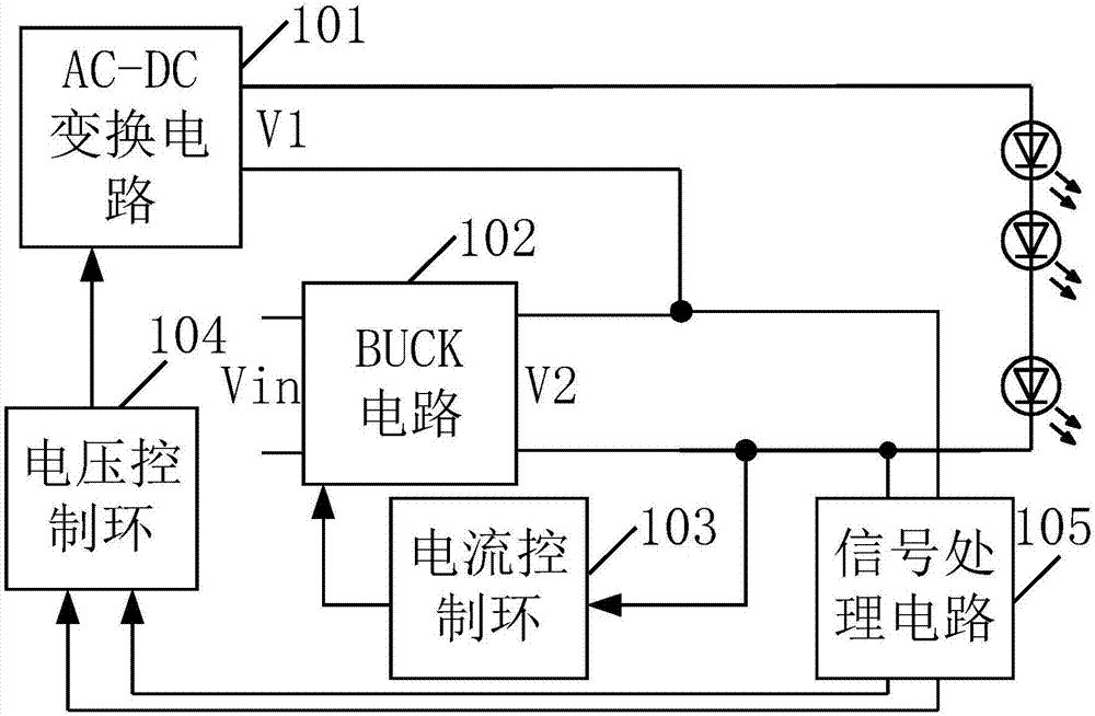
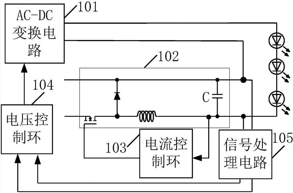
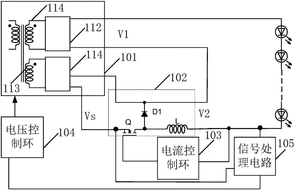
[0061] Specifically, such as figure 1 shown, the LED driver includes:

[0062] an AC-DC conversion circuit 101 and a BUCK circuit 102 connected in series at the output end;

[0063] The output terminal is connected to the current control loop 103 of the control terminal ...


PUM


Abstract

The invention discloses an LED driver. An AC-DC transfer circuit is connected with a BUCK circuit in series to drive an LED load; a current control ring controls a main switch tube of the BUCK circuit to realize steady flow output; after a signal processing circuit carries out peak holding treatment or valley holding treatment on the detection signal difference, the detection signal difference is output to the voltage control ring to control the main switch tube of the AC-DC transfer circuit to enable the sum of the output voltage of the AC-DC transfer circuit and the input voltage of the BUCK circuit to be larger than the LED load voltage or instantly equal to the LED load voltage and enable the output voltage average value of the BUCK circuit to be larger than or equal to a half of the ripple peak value of the output voltage of the AC-DC transfer circuit; the respond speed of the voltage control ring can be slow so as to guarantee a high RF value and realize PFC function, and the respond speed of the current control ring can be quick to guarantee the low ripple of the output current of the LED driver and protect the LED load from glitter phenomenon.

Description

technical field [0001] The invention relates to the technical field of LED driving, in particular to an LED driver. Background technique [0002] LED, as a new type of lighting device, is widely used in the lighting field due to its high luminous efficiency, but it usually requires a constant current drive. In the prior art, the LED driver for its constant current drive often adopts a single-stage scheme. [0003] The LED driver using a single-stage scheme needs to take into account the PFC (Power Factor Correction, power factor correction) function, that is, its control loop needs a very slow response speed to have a high PF (Power Factor, power factor) value. As a result, its control loop responds slower, which causes the output current to have a large ripple whose period is half the period of the input AC voltage. When the LED driver is connected to the load, this current ripple will cause the LED lamp to flicker, which will affect the service life of the LED lamp and ca...

Claims


Application Information

Patent Timeline
Patent Type & Authority Patents(China)
IPC IPC(8): H05B37/02
Inventor 俞杭冬李镇福
Owner INVENTRONICS HANGZHOU
Why Eureka
Try Eureka