Electric top toy started through rotation

A gyroscope and electric technology, applied in gyroscopes, toys, entertainment, etc., can solve the problems of affecting the rotation performance of toy gyroscopes, inconvenient carrying and playing, and affecting the fun of playing, so as to achieve unique and interesting gameplay, easy to carry and play, and improve the fun of playing Effect

Active Publication Date: 2015-06-17
ALPHA GRP CO LTD +2
View PDF4 Cites 5 Cited by
  • Summary
  • Abstract
  • Description
  • Claims
  • Application Information

AI Technical Summary

Problems solved by technology

But no matter how it changes so far, it is inseparable from the accessory of the gyro launcher, so it is necessary to carry an additional gyro launcher when carrying and playing, which makes it inconvenient to carry and play, and the launching operation is cumbersome and time-consuming, which affects the game pleasure
Moreover, there are too many internal parts of the electric gyro toy, the structure is complicated, and the cost is too high, which also affects the rotation performance of the toy gyro, and the rotation is unstable.

Method used


Image

  • Electric top toy started through rotation
  • Electric top toy started through rotation
  • Electric top toy started through rotation

Examples


Embodiment 1

[0027] like Figure 4As shown, the trigger switch 3 of this embodiment includes three ball switches. The optimal arrangement of the three ball switches is that the starting ends of the three ball switches are all facing outward, and the central axis of the gyroscope body 1 is the center of the circle. ° radially arranged on the circuit board 8, and all close to the edge of the circuit board 8, the circuit board 8 of this embodiment is also provided with a control chip 4, the ball switch and the motor 5 are connected to the control chip 4 through the circuit When the ball switch is triggered, the circuit is connected to the control chip 4, and the control chip 4 then sends a control signal to control the motor 5 to work and drive the gyro body 1 to rotate. The motor 5 in this embodiment is a DC motor, so when the gyroscope body 1 is manually rotated by hand, the motor 5 and the motor drive shaft 51 will rotate relative to each other, thereby generating pulses. Depending on the ...

Embodiment 2

[0030] like Figure 5 As shown, the trigger switch 3 of this embodiment includes three ball switches, wherein two ball switches are start ball switches 31, and the third ball switch is a steering ball switch 32, and the two start ball switches 31 are all start-up ends facing outwards. , the best installation method is that the two starting ball switches 31 are arranged on the same diameter, and are symmetrical with respect to the central axis of the gyro body 1. The balls of the starting ball switch 31 are all at the starting end; the turning ball switch 32 is installed in the gyro body 1 along the tangential direction of the gyro body 1 rotation, that is, the distance between the starting ends at its two ends and the axis of the gyro body 1 is equal. These three ball switches are all installed on the circuit board 8, and all are close to the edge position of circuit board 8, also be provided with control chip 4 on the circuit board 8 of this embodiment, ball switch and motor...


PUM


Abstract

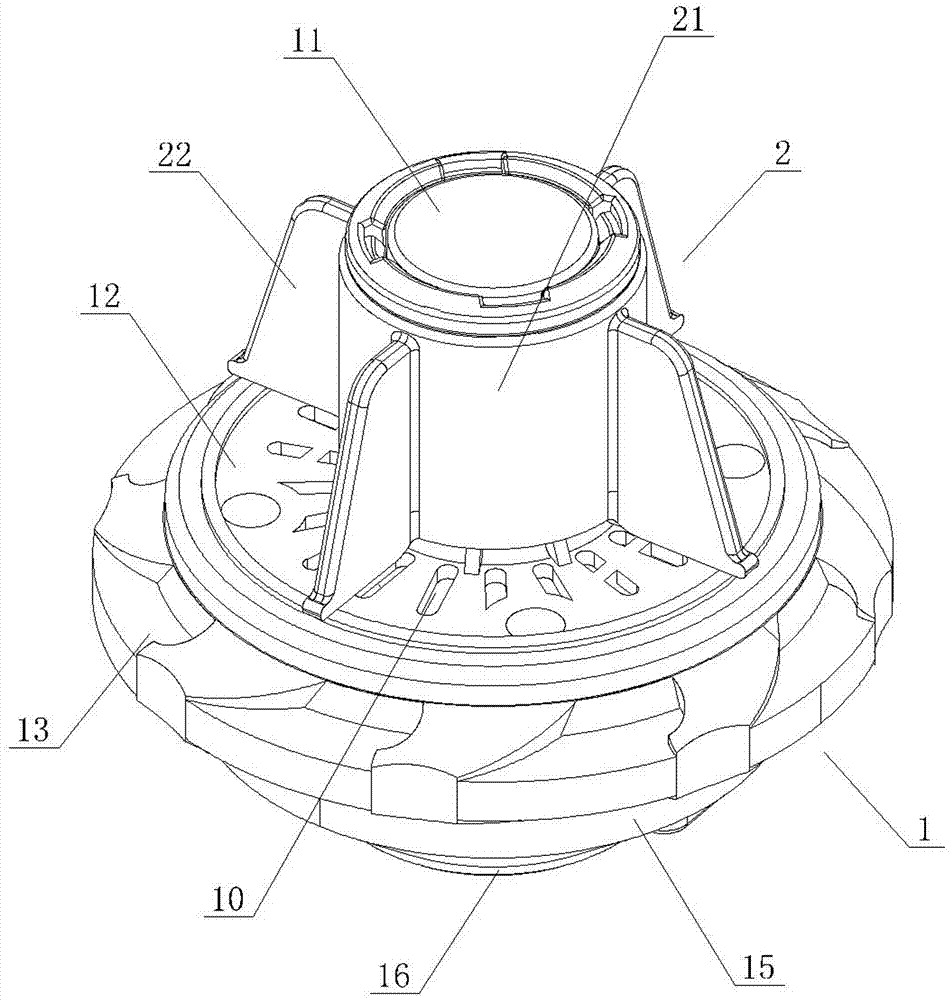
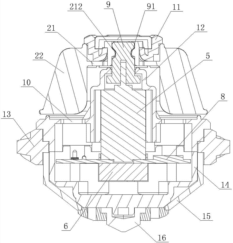
The invention discloses an electric top toy started through rotation. The electric top toy comprises a top body, a motor and a rotating body arranged on the upper portion of the top body in a sleeving mode, the motor and a motor drive shaft are connected with the top body and the rotating body respectively so that the rotating body can rotate relative to the top body, and a triggering switch is arranged in the top body. A user holds the rotating body and rotates the top body manually to trigger and close the triggering switch so that the motor can be connected with a power source to drive the top body to rotate, namely the electric top toy is started through rotation, a top emitter for emitting the top is omitted, cost is saved, and the electric top toy is convenient to carry and play, easy and fast to operate, ingenious in design, simple in structure and high in cost performance, improves playing enjoyment, can be manually started to rotate and accelerate and can be in the good graces of children as a playing method is fancy and interesting.

Description

technical field [0001] The invention relates to a toy top, in particular to an electric spinning top toy. Background technique [0002] Toy tops are very popular toys among children, but with the development of technology, toy tops are also developing and changing. At first, wooden tops needed to be wound with a whip and then accelerated by whipping. From the manual gyro toy that launches and rotates by cooperating with the pull bar, to the existing electric gyro toy that controls the rotation of the gyro through a remote controller. But no matter how it changes so far, it is inseparable from the accessory of the gyro launcher, so it is necessary to carry an additional gyro launcher when carrying and playing, which makes it inconvenient to carry and play, and the launching operation is cumbersome and time-consuming, which affects the game pleasure. Moreover, the electric top toy has too many internal parts, complex structure, and high cost, which also affects the rotation ...

Claims


Application Information

Patent Timeline
IPC IPC(8): A63H1/00A63H29/22
CPCA63H1/00
Inventor 蔡东青
Owner ALPHA GRP CO LTD
Why Eureka
Try Eureka