Using method for hoop hole drilling device

A processing device and clamp technology, applied in the field of fixtures, can solve problems such as unqualified clamp 1 and difficulty in avoiding deformation of arc segment 13, etc., and achieve the effects of convenient operation, simple structure and high processing accuracy

Inactive Publication Date: 2015-06-17
WUXI CITY SHENGFENG FORGING
View PDF0 Cites 3 Cited by
  • Summary
  • Abstract
  • Description
  • Claims
  • Application Information

AI Technical Summary

Problems solved by technology

[0002] like figure 1 The soft clamp 1 includes a circular arc section 13 and a horizontal section 11. If a circular hole 12 is processed on the horizontal section 11, the horizontal section 11 is positioned by using the method, and then the circular hole 12 is processed, but the The clamp 1 is made of a relatively thin and soft material. If only the horizontal section 11 is positioned, it will be difficult to avoid the deformation of the arc section 13 during the processing. Even if the processing of the round hole 12 meets the technical requirements, the Due to the deformation of the arc section 13, the processed clamp 1 is still a substandard product

Method used


Image

  • Using method for hoop hole drilling device
  • Using method for hoop hole drilling device
  • Using method for hoop hole drilling device

Examples


Embodiment Construction

[0014] The specific implementation manner of the present invention will be described below in conjunction with the accompanying drawings.

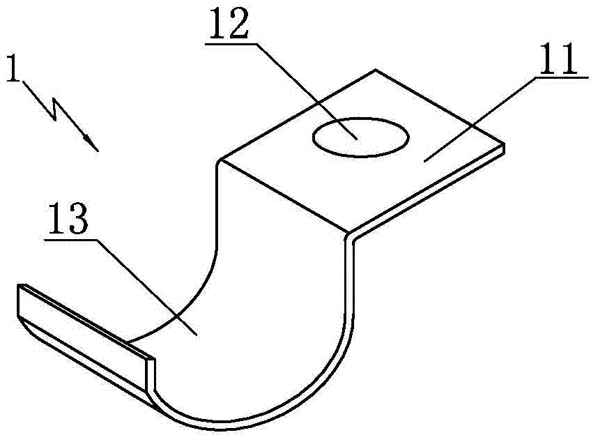
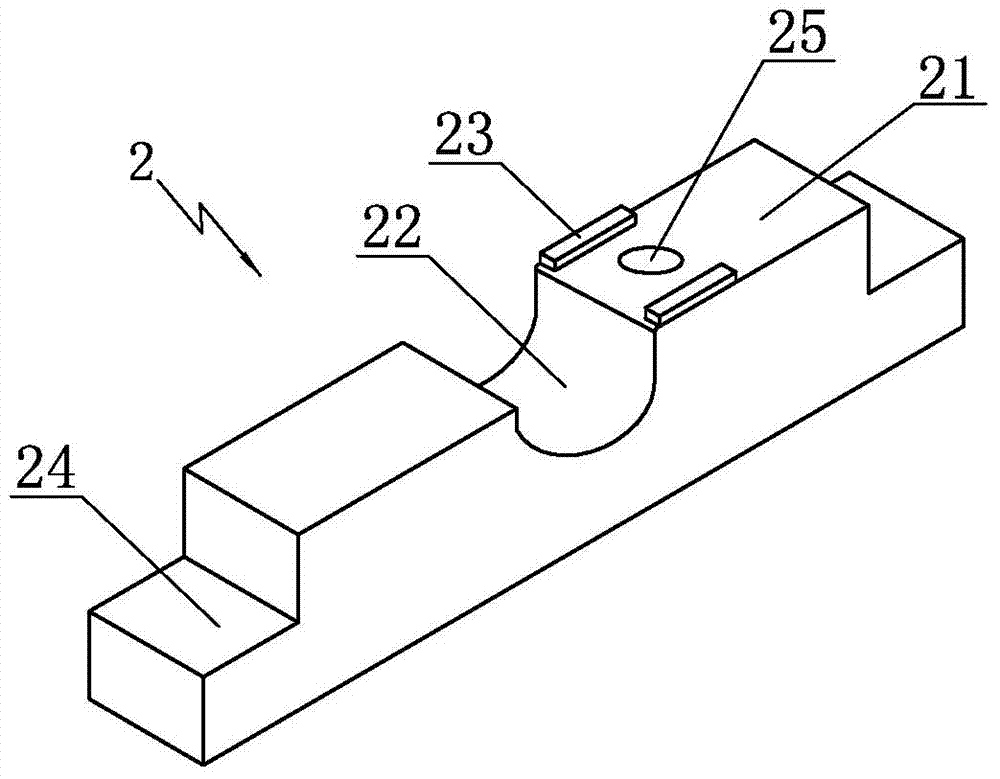
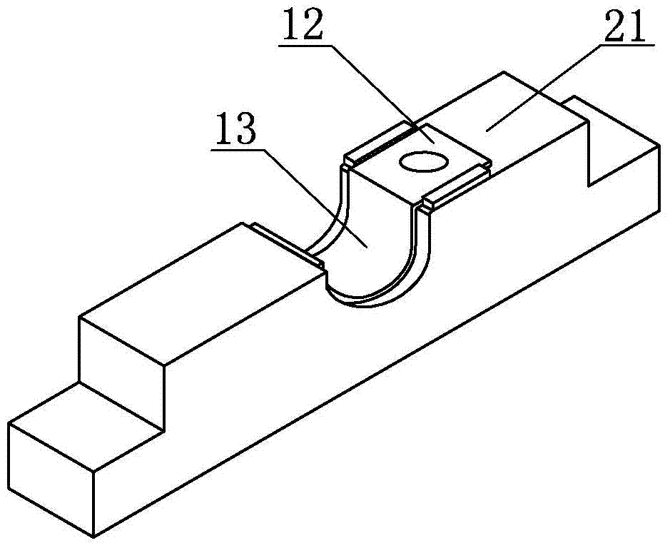
[0015] Such as Figure 1 to Figure 4 Shown, the present invention comprises die 2 and punch 3, and die 2 is rectangular block shape, and the width of die 2 is greater than the width of clamp 1, and the top surface 21 of die 2 has arc groove 22, uses Cooperate with the arc segment 13 of the clamp 1, there are positioning blocks 23 on both sides of the top surface 21, one end of the positioning block 23 is close to the edge of the arc groove 25, the height of the positioning block 23 is greater than the thickness of the clamp 1 and the positioning The distance between the blocks 23 is the same as the width of the clamp 1, which is conducive to positioning the horizontal section 11 of the clamp 1. On the top surface 21, a bore 25 is set between the positioning blocks 23. The size of the bore 25 is the same as that of the clamp. The circular ...


PUM


Abstract

The invention relates to a using method for a hoop hole drilling device. The using method comprises the following steps that 1, an arc section of a hoop and an arc groove of a female die are matched, and a horizontal section of the hoop is located between locating blocks on the female die; 2, a convex block on the female die presses the arc section of the hoop, and meanwhile a drill jig hole is located over the horizontal section of the hoop; 3, after the hoop is located, the hoop is drilled through the drill jig hole in a male die. The hoop hole drilling device is simple in structure, economical, practical, convenient to operate and high in machining precision.

Description

technical field [0001] The invention relates to the technical field of fixtures, in particular to a method for using a positioning device for drilling soft clamps. Background technique [0002] Such as figure 1 The soft clamp 1 includes a circular arc section 13 and a horizontal section 11. If a circular hole 12 is processed on the horizontal section 11, the horizontal section 11 is positioned by using the method, and then the circular hole 12 is processed, but the The clamp 1 is made of a relatively thin and soft material. If only the horizontal section 11 is positioned, it will be difficult to avoid the deformation of the arc section 13 during the processing. Even if the processing of the round hole 12 meets the technical requirements, the Due to the deformation of the arc section 13, the processed clamp 1 is still a substandard product. Contents of the invention [0003] Aiming at the above-mentioned shortcomings in the prior art, the present invention provides a meth...

Claims


Application Information

Patent Timeline
IPC IPC(8): B23B47/28B23Q3/06
CPCB23B47/28B23B2247/00B23Q3/062B23Q2703/10
Inventor 王磊
Owner WUXI CITY SHENGFENG FORGING
Why Eureka
Try Eureka