Supercharge Your Innovation With Domain-Expert AI Agents!

Circular heald frame

A circulating and heald frame technology, which is applied in healds, textiles, textiles and papermaking, etc., can solve the problems of loss and high energy consumption of the motor driving the heald frame, and achieve energy saving and high strength effects

Active Publication Date: 2015-06-17
苏州绾欣高新材料有限公司
View PDF7 Cites 0 Cited by
  • Summary
  • Abstract
  • Description
  • Claims
  • Application Information

AI Technical Summary

Problems solved by technology

[0003] More than two heald frames move up and down repeatedly to make the warp yarns form a shed for continuous weaving. This repeated up and down movement causes repeated loss of kinetic energy applied to the heald frames, resulting in huge energy consumption of the motor driving the heald frames. At the same time, because the current weaving machinery generally pursues high speed, it can only be achieved by continuously increasing the speed of the heald frame’s repeated movement. Constrained by the bottleneck of heald frame movement

Method used


Image

  • Circular heald frame
  • Circular heald frame
  • Circular heald frame

Examples


Embodiment 1

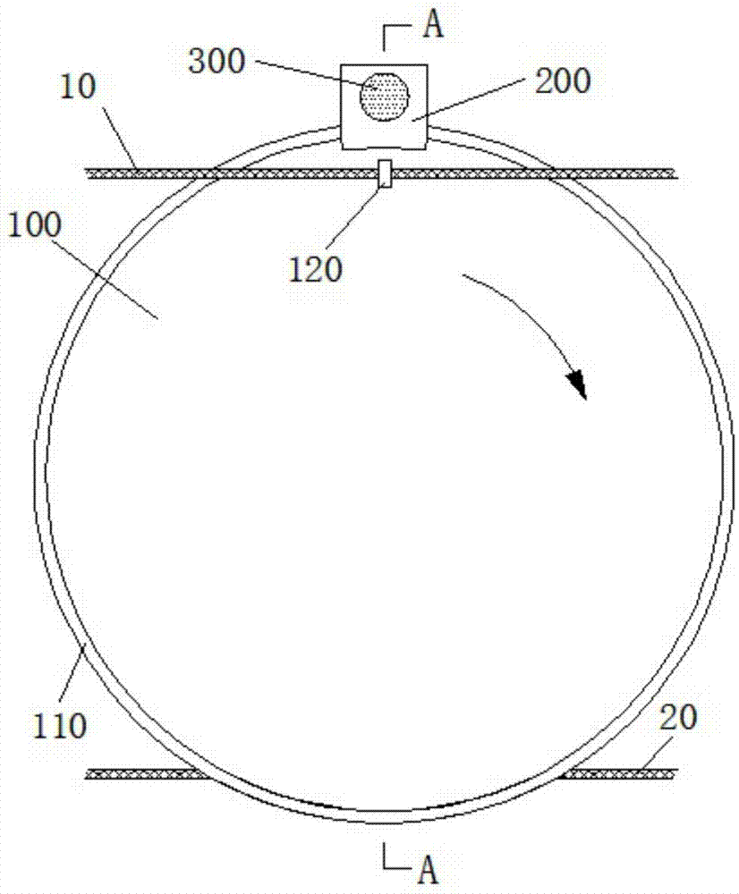
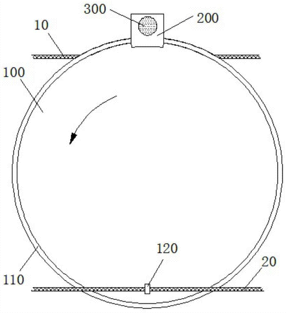
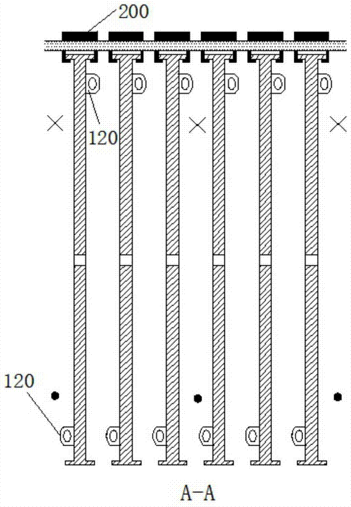
[0019] refer to figure 1 , figure 2 and image 3 , in the present embodiment, the circulating heald frame includes heald rings 120 passing through the warp yarns, and the heald rings 120 are respectively rotatably connected to the two sides of a driving disk 100, and the heald rings 120 distributed on both sides are pressed according to the driving disk 100 The center of the drive disc 100 is arranged symmetrically, the edge of the drive disc 100 is provided with a guide rail 110 or a groove, and one side of the drive disc 100 is slidably arranged in a drive clamp seat 200, and the drive clamp seat 200 is provided with a The guide rail 110 is a slide rail that is slidably matched, and the driving clamp seat 200 is provided with a driving structure that drives the driving disk 100. The driving disk 100 is arranged in an array along the axis to form a heald frame that makes the warp yarns 10, 20 layered up and down. Refer to image 3 , the heald loops 120 on the same driving ...

Embodiment 2

[0022] In another embodiment, on the basis of Embodiment 1, induction coils 400 are provided on both sides of the drive disc 100, magnets that cooperate with the induction coils 400 are provided in the heald ring 120, and the induction coils 400 Coil 400 makes the axis of described heald ring 120 point to the moving direction of warp yarn 10,20, and the axis of described heald ring 120 points to the moving direction of warp yarn 10,20 all the time, can keep the ring hole of heald ring 120 and warp yarn 10,20 to keep Proper distance, less friction. The magnet is an annular permanent magnet coaxially arranged with the heald ring 120, Figure 5 , the enlarged picture in the circle is the magnetic field direction diagram of the ring permanent magnet.


PUM


Abstract

The invention provides a circular heald frame. The circular heald frame comprises heald rings passing through warp yarns, wherein the heald rings are respectively rotationally connected to two surfaces of one driving disc, and the heald rings distributed on two surfaces are in symmetrical arrangement with respect to the center of the driving discs; the edges of the driving discs are provided with guide rails or grooves; one sides of the driving discs are arranged in a driving holder in a sliding mode; the driving holder is internally provided with a guide rail in sliding fit with the guide rails or the grooves and a driving mechanism driving the driving disc; the driving discs are arranged in an array mode along the axis so as to form the heald frame to enable warp yarns to be layered up and down. The rotation of the driving discs enables the heald rings which are rotationally connected to the disc surfaces to move vertically alternatively, and further the warp yarns complete the spinning motion in vertical alternative motion; because the heald rings are symmetrically distributed on the driving discs, the rotation of the heald rings and the driving discs always keeps centrifugal motion without losing kinetic energy, thereby achieving the aim of saving energy consumption.

Description

Technical field [0001] The invention relates to the field of loom equipment, in particular to a circulating heald frame for a loom. Background technique [0002] The heald frame is an important part of the loom, which is a frame with heald rods and driving parts connected by upper and lower beams and left and right side rails. After the piece heddle is arranged on the heald frame, the warp thread that penetrates into the piece heddle is integrated into one body, and with the movement of the heald lifting mechanism of the loom, the heald frame moves up and down according to the program of the shedding device, so that the warp yarn is layered and opened, and the weft yarn is placed in the warp yarn. Shuttle, and interweave into fabrics of different patterns. The heald is the main part of the heald frame, and the heald is made of wire, steel wire or steel sheet. There is a small hole (heald eye) in the middle for the warp thread to pass through. When each heddle controls a w...

Claims


Application Information

Patent Timeline
Patent Type & Authority Applications(China)
IPC IPC(8): D03C9/06
CPCD03C9/0683
Inventor 蔡国强
Owner 苏州绾欣高新材料有限公司
Features
  • R&D
  • Intellectual Property
  • Life Sciences
  • Materials
  • Tech Scout
  • Unparalleled Data Quality
  • Higher Quality Content
  • 60% Fewer Hallucinations
Learn More