Multi-hole adjustable multi-variable-load hydraulic buffer

A hydraulic shock absorber, adjustable technology, applied in the field of hydraulic shock absorbers, can solve the problems of inability to shock buffer, impact additional peak buffer performance is not very good, performance degradation, etc.

Active Publication Date: 2015-06-17
CHINA THREE GORGES UNIV
View PDF5 Cites 30 Cited by
  • Summary
  • Abstract
  • Description
  • Claims
  • Application Information

AI Technical Summary

Problems solved by technology

For load shocks with fluctuating changes, the commonly used hydraulic shock absorbers only adjust the main peak value of the shock, and the buffer performance of the additional peak value of the shock is not very good, and it is accompanied by certain shocks and vibrations, which cannot be smoothly buffered.
In addition, the existing buffers are only designed for a specific single working condition and load, and the vibration damping performance is good under the design working condition, but when the actual working condition and load change, its performance decreases

Method used


Image

  • Multi-hole adjustable multi-variable-load hydraulic buffer
  • Multi-hole adjustable multi-variable-load hydraulic buffer
  • Multi-hole adjustable multi-variable-load hydraulic buffer

Examples


Embodiment Construction

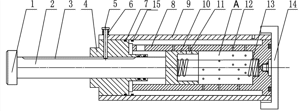
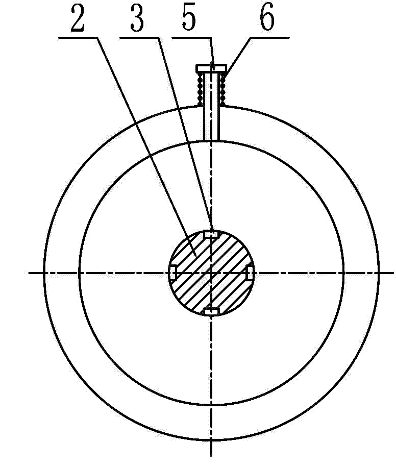
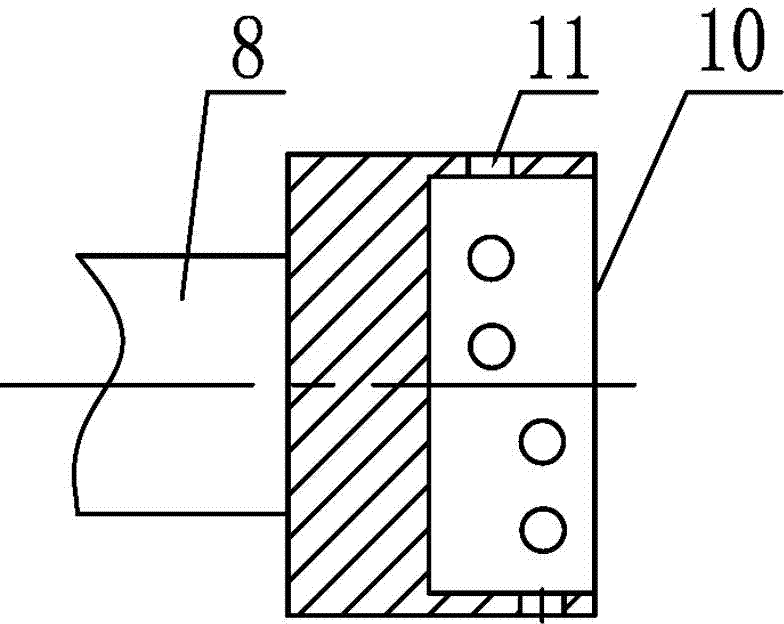
[0019] The structure of the present invention is as figure 1 -3 shows: a porous adjustable variable load hydraulic buffer, including a base 14, an inner cylinder 8, an outer cylinder 9 and the base 14 are rigidly connected concentrically; the inner cylinder 8 is circumferentially directed to the inner cylinder damping hole 12; The piston 10 is connected to the bottom of the inner cylinder 8, and the piston rod 2 is connected to the piston 10. The piston rod 2 and the piston 10 reciprocate under the action of the return spring 13 and the load. A piston damping hole 11 is opened on the outer wall of the piston 10. An adjustment knob 1 is provided, and the adjustment knob 1 can adjust the angle direction of the piston 10. The positioning pin 5 passes through the outer cylinder 9 and the end cover 4 to cooperate with the guide groove 3 on the piston rod 2, and through the guide groove of the piston rod 2, the piston 10 rotation direction positioning.

[0020] When the piston 10 m...


PUM


Abstract

A multi-hole adjustable multi-variable-load hydraulic buffer comprises a base. An inner cylinder and the outer cylinder are concentrically and rigidly connected with the base. The inner cylinder is provided with inner cylinder damping holes in the circumferential direction. A reset spring is connected with a piston and the bottom of the inner cylinder. A piston rod is connected with the piston. Piston damping holes are formed in the outer wall of the piston. An adjudging knob is arranged at the front end of the piston rod. A locating pin penetrates through the outer cylinder and an end cover to be matched with a guide groove in the piston rod, and the rotation direction of the piston is fixed through the guide groove of the piston rod. According to the changing curve of loads, the damping holes according with the changing rule of the loads are formed in the wall surface of the inner cylinder, and the piston damping holes are formed along the outer wall of the piston; in the buffering process, a damping curve consistent with the changing curve of the loads is formed, and uniform buffering is achieved. Through the adjusting knob and the guide groove in the front end face of the piston rod, the rotation direction of the piston can be adjusted, the matching rule of the damping holes in the wall surface of the inner cylinder and the damping holes in the piston can be changed, in this way, the damping curve of the buffer is changed, and different loads are buffered.

Description

technical field [0001] The invention relates to the technical field of buffering, in particular to a hydraulic buffer adaptable to variable loads and good buffering performance. Background technique [0002] In daily life and production practice, a large amount of vibration and shock exist in mechanical equipment, which affects the normal operation of mechanical equipment. With the development of science and technology, people gradually realize the harm of vibration and shock to mechanical equipment, and put forward various methods to reduce the shock. Among them, adding a buffer between the impact parts is the most common solution. Buffers are widely used in weapons and equipment, lifting transportation, port machinery, metallurgical machinery, vehicles and other mechanical equipment. It is a safety protection device for slowing down rigid collisions during equipment operation. The buffer can prolong the action time of the impact load, absorb and convert the energy of the...

Claims


Application Information

Patent Timeline
Patent Type & Authority Applications(China)
IPC IPC(8): F16F9/512F16F9/44F16F9/18
CPCF16F9/18F16F9/44F16F9/5126
Inventor 赵新泽汪坤徐翔赵美云秦红玲
Owner CHINA THREE GORGES UNIV
Why Eureka
Try Eureka