Sealing device for valve shaft of high-temperature butterfly valve

A technology of sealing device, butterfly valve valve, applied in the direction of shaft sealing, valve device, valve details, etc.

Inactive Publication Date: 2015-06-17
洛阳兴罡石化设备有限公司
View PDF6 Cites 2 Cited by
  • Summary
  • Abstract
  • Description
  • Claims
  • Application Information

AI Technical Summary

Problems solved by technology

[0004] The purpose of the present invention is to overcome the defects of the existing high-temperature butterfly valve shaft sealing device, and provide a valve shaft sealing device for a high-temperature valve shaft with a new structure. The technical problem to be solved is to make it pass through the valve shaft. The boss an

Method used


Image

  • Sealing device for valve shaft of high-temperature butterfly valve
  • Sealing device for valve shaft of high-temperature butterfly valve
  • Sealing device for valve shaft of high-temperature butterfly valve

Examples


Embodiment Construction

[0033] In order to further explain the technical means and effects of the present invention to achieve the intended purpose of the invention, the specific implementation and structure of a sealing device for a high-temperature butterfly valve shaft proposed according to the present invention will be described below in conjunction with the accompanying drawings and preferred embodiments. , features and their effects are described in detail below.

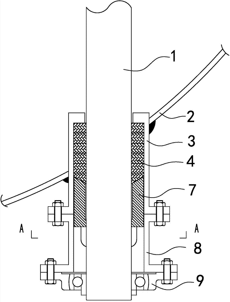
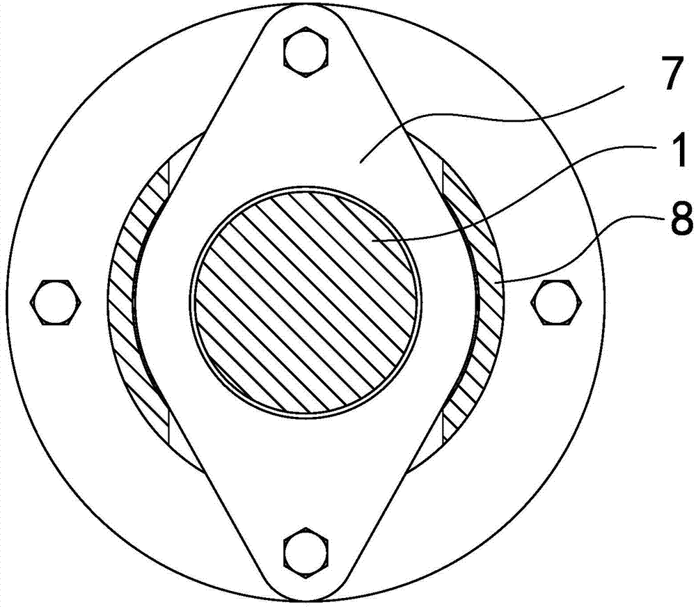
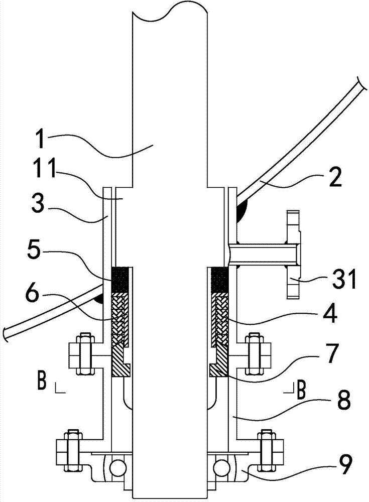
[0034] see image 3 and Figure 4 , which is a cross-sectional view of a sealing device for a valve shaft of a high-temperature butterfly valve and a B-B cross-sectional view thereof according to an embodiment of the present invention. It can be seen from the figure that the embodiment of the present invention is a valve shaft sealing device for a high temperature butterfly valve, including a valve shaft 1 , a stuffing box 3 , a composite sealing body 5 , a packing 4 , a compression sleeve 6 , and a packing gland 7 .

[0035] Among...


PUM


Abstract

The invention relates to a sealing device for a valve shaft of a high-temperature butterfly valve. The sealing device comprises a valve shaft, a packing box, a composite sealing body, packing and a packing pressing cover, wherein the valve shaft is provided with an annular sealing lug boss; the packing box is arranged on the outer side of the valve shaft; the packing box is internally and sequentially provided with the composite sealing body, the packing and the packing pressing cover which are tightly connected from the direction close to the lug boss to the direction far away from the lug boss; and the packing pressing cover is fixed on the packing box, and the packing is pressed. The lug boss is in end face sealing with the composite sealing body, a gap with the size of 5cm or more than 5cm is formed between the lug boss and the packing box, and a gap with the size of 5cm or more than 5cm is formed between a pressing sleeve and the valve shaft. The composite sealing body can be finely adjusted when the valve shaft is deformed, even bent at a high temperature, so that the valve shaft is still tightly combined with the composite sealing body and the pressing sleeve, and the friction force is not changed. The sealing device is provided with a blowing opening 4, and an external wind force is introduced from the blowing opening to blow away a medium between the valve shaft and the sealing device, so that the sealing device is prevented from being blocked.

Description

technical field [0001] A sealing device for a valve shaft of a high-temperature butterfly valve, in particular to a sealing device for a valve shaft of a high-temperature butterfly valve in a petrochemical device. Background technique [0002] see figure 1 and figure 2 , which is the sectional view of the current domestic high-temperature butterfly valve shaft and its sealing device and its A-A sectional view. It can be seen from the figure that the sealing device of the valve shaft of the high temperature butterfly valve includes a stuffing box 3, a stuffing 4, a gland 7 and a first space, and the first space 71 is used to press and fix the gland so that the gland 7 holds the stuffing 4 Compress to make it tightly fill the gap between the valve shaft and the stuffing box 3 to realize radial sealing. At this time, there must be a certain friction force between the valve shaft and the packing when it rotates. When the valve shaft deforms or even bends at high temperature,...

Claims


Application Information

Patent Timeline
IPC IPC(8): F16K41/02
CPCF16K41/023
Inventor 张炳罡
Owner 洛阳兴罡石化设备有限公司
Why Eureka
Try Eureka