Three-dimensional encapsulation surface antenna capable of achieving gap embedding amplitude calibration

A three-dimensional packaging, amplitude calibration technology

Inactive Publication Date: 2015-06-17
SOUTHEAST UNIV
View PDF2 Cites 0 Cited by
  • Summary
  • Abstract
  • Description
  • Claims
  • Application Information

AI Technical Summary

Problems solved by technology

However, the horn antenna is usually non-planar, incompatible with the planar circuit process, and has a large geometric size, which limits its application in the packaging structure
In recent years, the substrate-integrated waveguide horn antenna developed based on substrate-integrated waveguide technology has the characteristics of small size, light weight, and easy planar integration. However, the gain of the traditional substrate-integrated waveguide horn antenna is relatively low. One of the reasons is that the aperture The amplitude of the electroma

Method used


Image

  • Three-dimensional encapsulation surface antenna capable of achieving gap embedding amplitude calibration
  • Three-dimensional encapsulation surface antenna capable of achieving gap embedding amplitude calibration
  • Three-dimensional encapsulation surface antenna capable of achieving gap embedding amplitude calibration

Examples


Embodiment Construction

[0022] The present invention will be further described below in conjunction with drawings and embodiments.

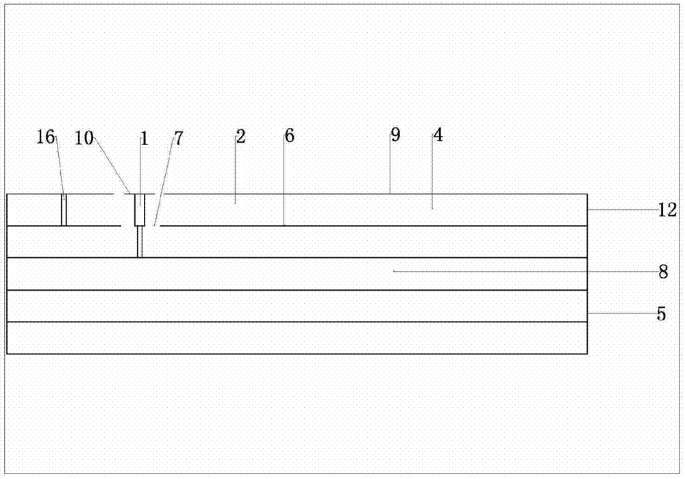
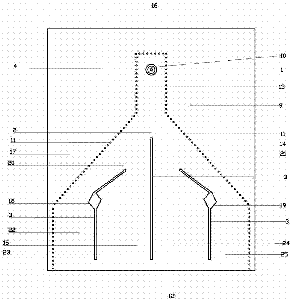
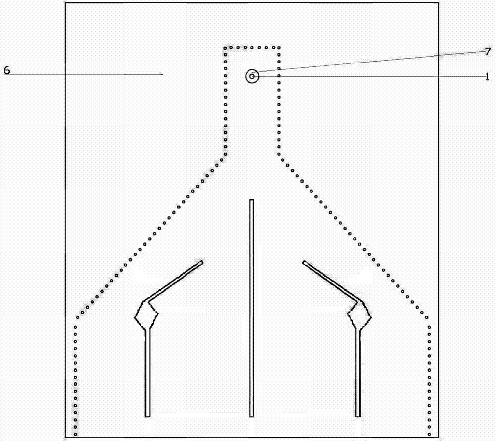
[0023] The embodiment adopted by the present invention is: the three-dimensional encapsulation surface antenna with embedded amplitude calibration in the gap includes a metallized vertical via hole feeder 1 arranged on a dielectric substrate 4, a substrate integrated waveguide horn antenna 2 and a gap 3, and the dielectric substrate 4 is placed on the dielectric substrate 4. The top of the three-dimensional package 5; the metallized vertical via hole feeder 1 is connected to the internal circuit 8 of the three-dimensional package 5; the substrate integrated waveguide horn antenna 2 is composed of a bottom metal plane 6 located on one side of the dielectric substrate 4 and located on the other side of the dielectric substrate 4. The top metal plane 9 on one side and the metallized via hole horn side wall 11 passing through the dielectric substrate 4 to connect the bottom ...


PUM


Abstract

The invention relates to a horn antenna, in particular to a three-dimensional encapsulation surface antenna capable of achieving gap embedding amplitude calibration. The antenna comprises a metallization perpendicular via hole feeder line (1), a horn antenna body (2) and gaps (3), wherein the metallization perpendicular via hole feeder line (1), the horn antenna body (2) and the gaps (3) are integrated on a dielectric substrate (4) which is located on the topmost face of a three-dimensional encapsulation part (5), and one end of the metallization perpendicular via hole feeder line (1) is connected with an internal circuit (8). The horn antenna body (2) is composed of a bottom face metal plane (6), a top face metal plane (9) and metallization via hole side walls (11), the gaps (3) are formed in the bottom face metal plane (6) and the top face metal plane (9), and four sub-horns are formed in the horn antenna body (2) through the middle gap (17), the left gap (18) and the right gap (19), and electromagnetic wave energy in the antenna is distributed on an antenna aperture face (12) at equal amplitude. The aperture efficiency of the antenna can be improved.

Description

technical field [0001] The invention relates to a horn antenna, in particular to a three-dimensional packaged surface antenna with amplitude calibration embedded in a slot. Background technique [0002] Using micro-assembly technology, a radio frequency system can be placed in a package, for which the antenna also needs to be integrated on the surface of the package. It is a natural way to integrate a patch antenna on the surface of the package, but the main radiation direction of the patch antenna is the normal direction of the surface, and the main radiation direction we sometimes need is along the surface direction. If the horn antenna is integrated on the surface of the package, the radiation along the surface direction can be realized. However, horn antennas are usually non-planar, incompatible with planar circuit technology, and have large geometric dimensions, which limits their application in packaging structures. In recent years, the substrate-integrated waveguide...

Claims


Application Information

Patent Timeline
IPC IPC(8): H01Q13/02H01Q3/28
Inventor 赵洪新鲁询询殷晓星
Owner SOUTHEAST UNIV
Why Eureka
Try Eureka