Upper die fixed type fin forming machine

A molding machine, fixed technology, applied in the directions of molding tools, positioning devices, feeding devices, etc., can solve the problems of inability to adjust, low guiding accuracy, etc., and achieve the effect of eliminating the effect of accuracy

Active Publication Date: 2015-06-24
NINGBO RONGZHI AUTOMATION TECH
View PDF8 Cites 9 Cited by
  • Summary
  • Abstract
  • Description
  • Claims
  • Application Information

AI Technical Summary

Problems solved by technology

However, the above-mentioned high-precision reciprocating feeding mechanism has the following disadvantages: the pusher rod is a whole in its structure, and when the left and right pushers cannot be horizontally and parallelly fed due to the difference in the gap, they cannot be adjusted.
In addition, the front and rear guide points of the push rod are located inside the hinge seat, the distance between the guide points is too small, and the guide accuracy is not high

Method used


Image

  • Upper die fixed type fin forming machine
  • Upper die fixed type fin forming machine
  • Upper die fixed type fin forming machine

Examples


Embodiment Construction

[0034] The present invention will be further described in detail below in conjunction with the accompanying drawings and embodiments.

[0035] Such as Figure 1-13 Shown is a preferred embodiment of the present invention.

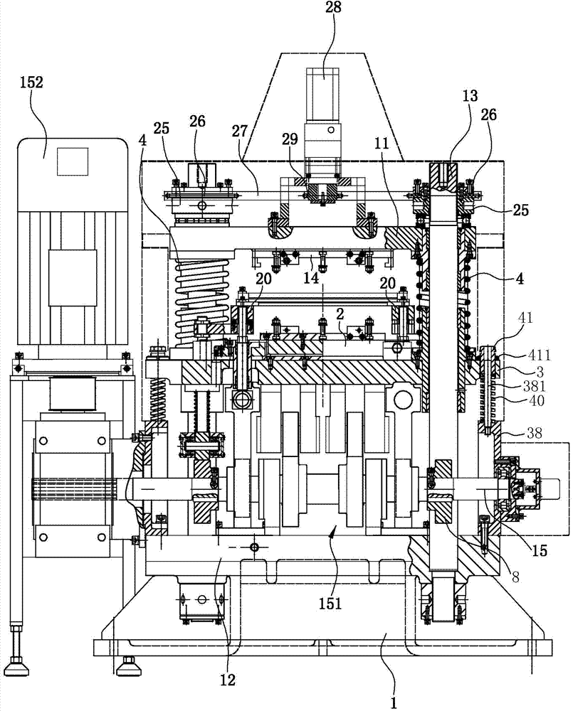
[0036] A fixed upper mold fin forming machine, comprising

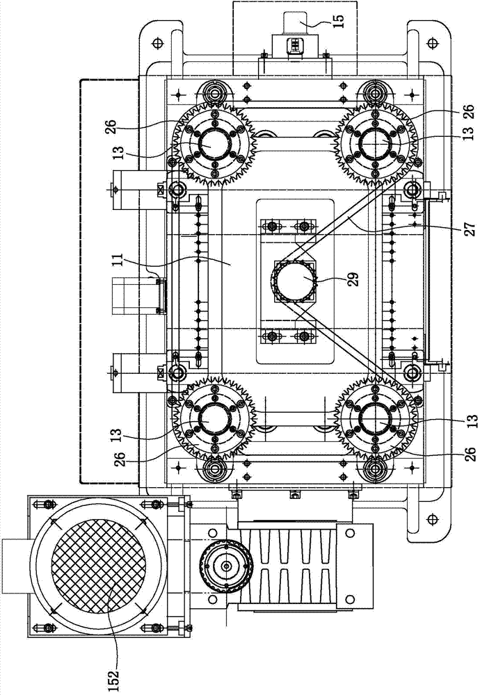
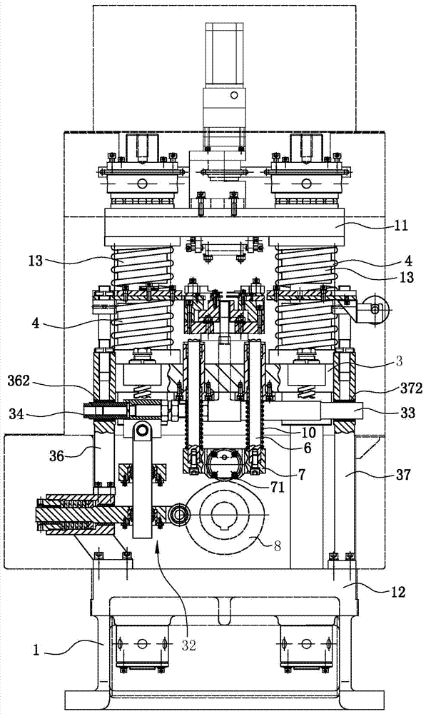
[0037] Frame 1, it is made up of upper machine board 11, lower machine board 12 and the guide post 13 that is located between upper machine board 11 and lower machine board 12, upper machine board 11 can move up and down relative to guide post 13, upper machine board On the 11, a patrix mounting plate 14 is installed, and the patrix mounting plate 14 is used to fix the patrix, and the guide post 13 above the upper machine plate 11 is provided with a position-limiting structure that carries out upper limit to the upper machine plate 11.

[0038] Lower template 3 is located at the inner bottom of frame 1 and can slide up and down along guide pillar 13. Lower template 3 is provided with a lower mold...


PUM


Abstract

The invention relates to an upper die fixed type fin forming machine. The upper die fixed type fin forming machine is characterized by comprising a machine frame, a lower die plate, a retaining spring, two shifting rods, a transmission shaft, a cam driving structure and a stripping structure, wherein the machine frame is composed of an upper machine plate, a lower machine plate and a guiding column, an upper die installation plate is installed on the upper machine plate, the lower die plate is arranged on the lower portion inside the machine frame and can slip up and down along the guiding column, a lower die installation sliding plate is arranged above the lower die plate, the guiding column is sleeved with the retaining spring which is supported between the upper machine plate and the lower die plate, the left and right shifting rods are arranged vertically in a spaced mode, penetrate through the lower die plate upwards and then are connected with the lower die installation sliding plate, the transmission shaft is driven by a motor to rotate, the cam driving structure is arranged inside the machine frame, located below the lower die plate and arranged between the transmission shaft and the lower die plate, and the stripping structure is arranged between the lower die plate and the upper machine plate. Due to the fact that the upper die does not need to do the vertical stamping action, an upper driving shaft, an upper die plate and a cam driving structure between the upper driving shaft and the upper die plate in the prior art can be eliminated, and the precision influence generated by abrasion of a universal coupler in an existing structure is eliminated.

Description

technical field [0001] The invention belongs to the field of stamping and forming machine tools dedicated to fins, in particular to a fin forming machine with a fixed upper die. Background technique [0002] Aluminum fins are widely used in automotive aluminum water tank radiators, parallel flow condensers, parallel flow evaporators, radiators or surface coolers, variable air volume air conditioning cabinets, fan coils and heat exchangers. The main function of the component is to dissipate heat. The plate-fin heat exchanger has the advantages of compact structure, light weight, and high heat exchange efficiency, especially the heat exchange efficiency is 30% higher than other heat exchangers. Fins are the key components of plate-fin heat exchangers, accounting for more than 80% of the volume of the entire heat exchanger. The precision of fins directly affects the heat transfer efficiency, reliability and safety performance of plate-fin heat exchangers. [0003] There are fo...

Claims


Application Information

Patent Timeline
Patent Type & Authority Applications(China)
IPC IPC(8): B21D53/04B21D37/10B21D45/08B21D37/12B21D43/02
CPCB21D37/10B21D37/12B21D43/02B21D45/08B21D53/04
Inventor 王荣董明智倪泉斌毛国平
Owner NINGBO RONGZHI AUTOMATION TECH
Why Eureka
Try Eureka