Novel shaft sleeve unit

A bushing, a new type of technology, applied to the parts of boring machine/drilling machine, the drilling template for the workpiece, the measurement of positioning in the boring machine/drilling machine, etc., can solve the problems of difficult correction, affecting the shape quality, one-way clearance, etc.

Inactive Publication Date: 2015-06-24
李洋
View PDF0 Cites 0 Cited by
  • Summary
  • Abstract
  • Description
  • Claims
  • Application Information

AI Technical Summary

Problems solved by technology

[0002] At present, the verticality of the drilling cannot be guaranteed, which causes the axis of the hole to deviate, and it is difficult to correct, which in turn leads

Method used


Image

  • Novel shaft sleeve unit

Examples


Embodiment Construction

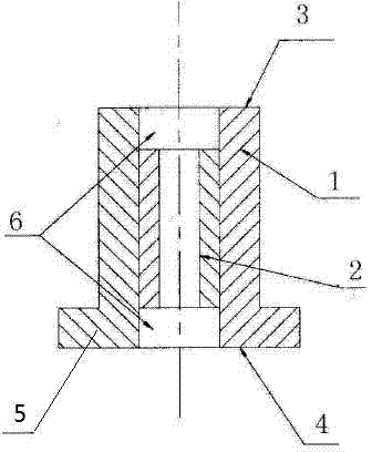
[0011] Such as figure 1 As shown, a new type of bushing, a bushing 2 is coaxially arranged in the jig shell 1, and a through hole is arranged in the bushing 2; the two ends of the jig shell 1 are respectively a small circle action surface 3 and a large circle action surface 4. An end plane 5 is provided on the large circle action surface 4, which is tangent to the corresponding circle of the small circle action surface 3. The length of the shaft sleeve 2 is less than that of the jig casing 1 , and there are drill chip storage grooves 6 at both ends of the inner circumference of the jig casing 1 .

[0012] The part to be drilled in the device is an inclined plane, and the large circular action surface 4 of the verticality-guided drilling mold coincides with the surface of the part, and the hole is processed through the guidance of the shaft sleeve 2; as shown in Figure 4, the part to be drilled is provided with a boss, and the drill The position of the hole is close to the pos...


PUM


Abstract

The invention discloses a novel shaft sleeve unit. The novel shaft sleeve unit is characterized in that a shaft sleeve is co-axially arranged in a drill jig shell and internally provided with a through hole; two ends of the drill jig are formed into a small-circle action surface and a large-circle action surface, and a plane is formed on the large-circle action surface and tangent with the small-circle action surface. The novel shaft sleeve unit is small in size, portable, convenient to use, easy to operate and higher in drilling precision.

Description

technical field [0001] The invention relates to a verticality-guided drilling mold, in particular to a novel shaft sleeve. Background technique [0002] At present, the verticality of the drilling cannot be guaranteed, which causes the axis of the hole to deviate, and it is difficult to correct, which in turn leads to the deflection of the dimple, and a one-way gap appears after the rivet or bolt is fastened, which affects the appearance quality and delays the delivery of the product. Contents of the invention [0003] In order to solve the above problems, the present invention designs a new type of shaft sleeve, which is firmly fixed, easy to install, simple in structure, and can be integrally formed, thereby reducing production costs. [0004] Technical scheme of the present invention is: [0005] A new type of shaft sleeve is characterized in that: a shaft sleeve (2) is coaxially provided in the jig case (1), and a through hole is provided in the shaft sleeve 2); the t...

Claims


Application Information

Patent Timeline
IPC IPC(8): B23B49/02B23B47/28
CPCB23B49/02
Inventor 李洋
Owner 李洋
Why Eureka
Try Eureka