LED module installing mechanism

A technology of LED module and installation mechanism, which is applied to identification devices, lighting devices, components of lighting devices, etc., can solve the problems of inability to achieve adjustment, complicated methods, instability, etc., and achieve convenient operation, precise control, and adjustment methods. simple effect

Active Publication Date: 2015-06-24
GLUX VISUAL EFFECTS TECH (SHENZHEN) CO LTD
View PDF5 Cites 34 Cited by
  • Summary
  • Abstract
  • Description
  • Claims
  • Application Information

AI Technical Summary

Problems solved by technology

[0005] For this reason, the technical problem to be solved by the present invention is that the way of adjusting the plane gap of the LED module in the prior art is complicated and unstable, and the adjustment of the flatness perpendicular to the plane direction of the LED module cannot be realized, and it provides a simple adjustment operation , the adjustment effect is stable, and the LED module installation mechanism can simultaneously adjust the flatness perpendicular to the direction of the LED module and the plane gap of the LED module

Method used


Image

  • LED module installing mechanism
  • LED module installing mechanism
  • LED module installing mechanism

Examples


Embodiment 1

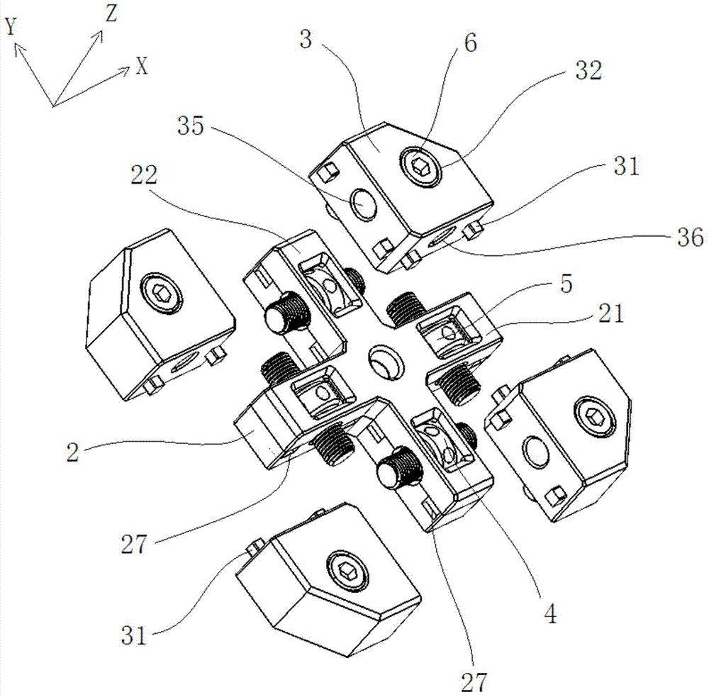
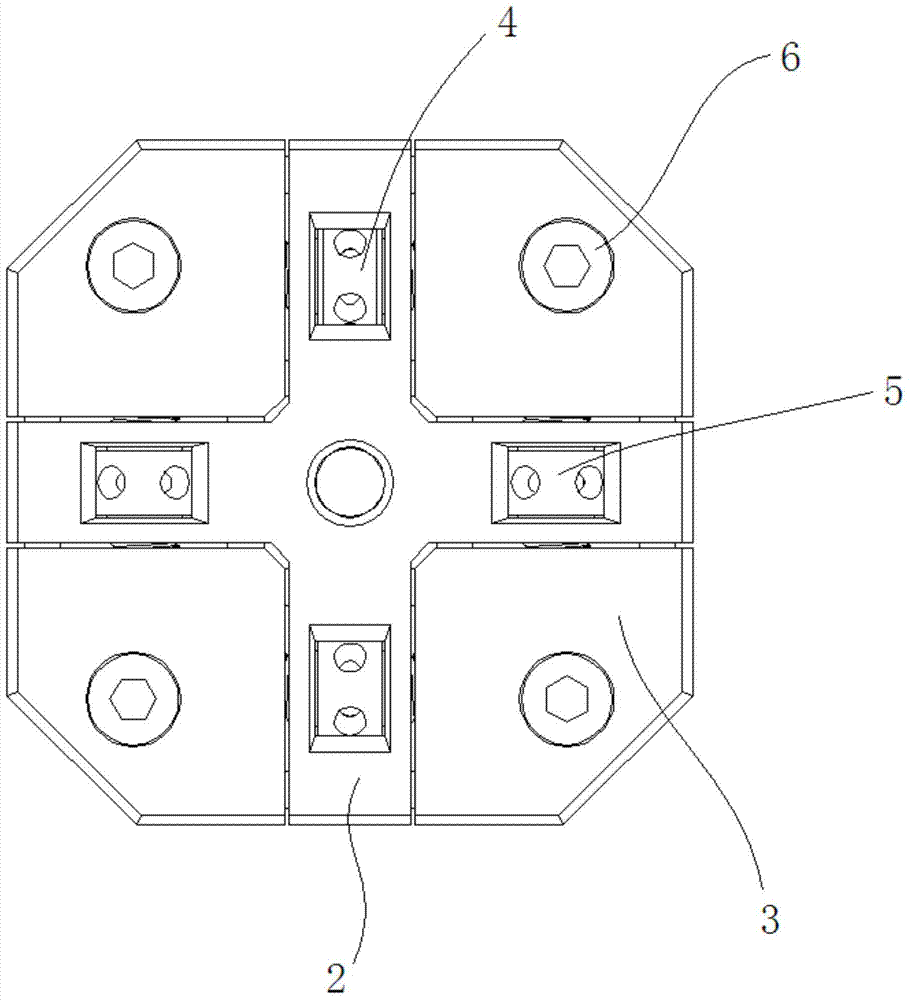
[0048] Refer to Figure 2 ~ Figure 5 , The LED module installation mechanism of the present invention includes a fixed frame 2, at least two movable blocks 3, and a gap adjustment mechanism installed on the fixed frame 2. among them

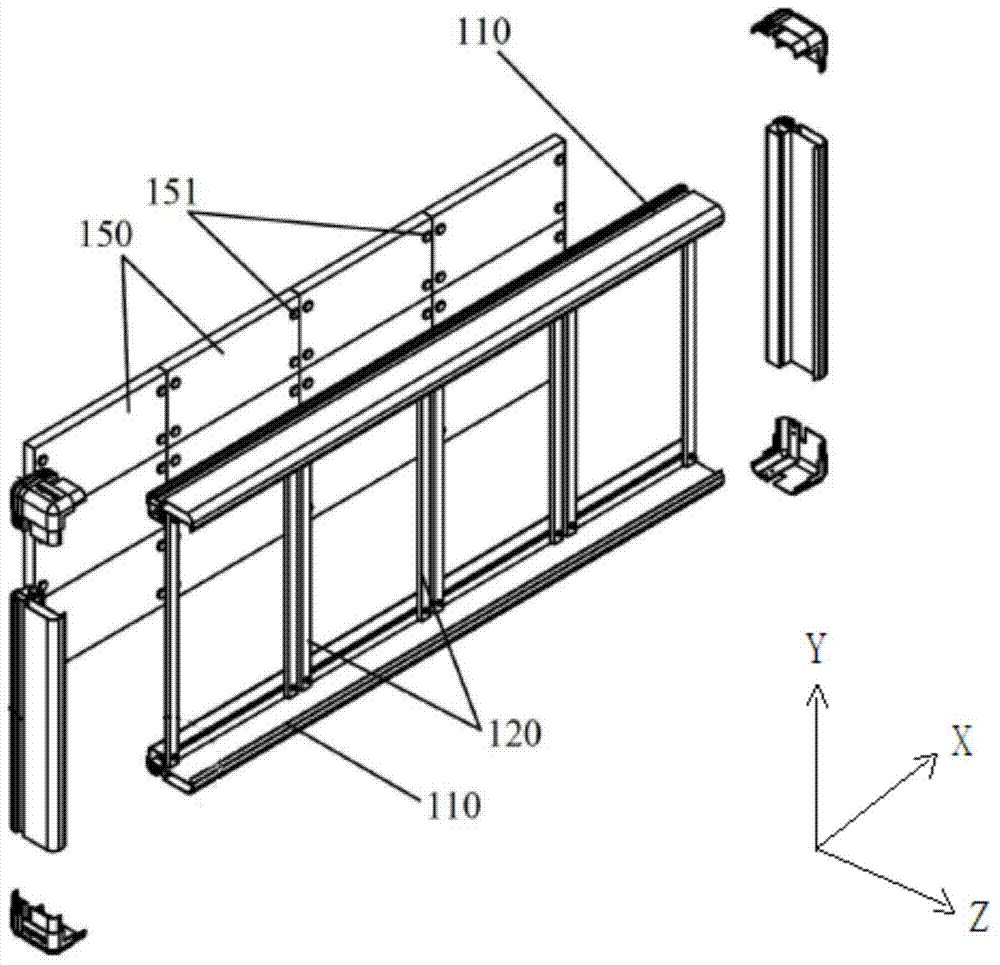
[0049] The fixing frame 2 can take various shapes. In this embodiment, it is preferably in the shape of a cross and is composed of a horizontal frame 21 and a vertical frame 22. The extension direction of the horizontal frame 21 is defined as the X-axis direction. The extension direction of the vertical frame 22 is the Y-axis direction;

[0050] The movable block 3 is provided with four blocks, which are arranged on both sides of the horizontal frame 21 and the vertical frame 22, and are distributed in a "tian" shape. The movable blocks 3 are arranged on both sides of the horizontal frame 21 It can move along the X-axis direction, the movable blocks 3 arranged on both sides of the vertical frame 22 can move along the Y-axis direction, and each movabl...

Embodiment 2

[0074] The first embodiment of the present invention is basically the same as the first embodiment, and the difference from the first embodiment is that the fixing frame 2 in the second embodiment has a "T" shape, such as Figure 17 with Figure 18 As shown, the vertical frame 22 of the fixed frame 2 is connected to the horizontal frame 21. In this embodiment, it is preferably connected to the middle position of the horizontal frame 21. Two ends of the horizontal frame 21 are respectively provided with The movable block 3 is connected together in the Y-axis direction and the Y-axis adjustment screw 5 is provided on the vertical frame 22 with an X-axis adjustment screw 4 that connects the movable block 3 together in the X-axis direction. The movable block 3 is all installed on the fixed frame 2 through the X-axis and Y-axis adjustment screws, and the LED module 100 installed on the movable block 3 can also pass through a number of this embodiment The LED module installation mecha...


PUM


Abstract

The invention discloses an LED module installing mechanism. The LED module installing mechanism comprises a fixed rack (2), a gap adjusting mechanism on the fixed rack (2), and at least two moving blocks (3) movably connected with the fixed rack (2). LED modules (100) are arranged on the moving blocks (3). The two ends of the gap adjusting mechanism are connected with the moving blocks (3) respectively. By adjusting the moving block (3) on the two sides to move away or get close to each other, a gap between the LED modules (100) arranged on the moving blocks (3) is adjusted. The invention belongs to the technical field of LED modules and LED display screens. According to the LED module installing mechanism, the technical problems in the prior art that the method for adjusting the planar gap between the LED modules is complex and unstable, and the adjustment on the planeness which is perpendicular to the planar direction of the LED modules is unable to achieve are solved. The LED module installing mechanism is particularly applicable to adjusting the planeness perpendicular to the direction of the LED modules and the planar gap between the LED modules, the adjusting operation is simple, and the adjusting effect is stable.

Description

Technical field [0001] The invention belongs to the field of LED modules, and particularly relates to an LED module installation mechanism. Background technique [0002] At present, LED display screens are mostly used in various indoor and outdoor venues for advertising and stage layout. People have higher and higher requirements for the display effect of LED displays. Large-scale LED display screens commonly used at present are assembled by multiple LED modules through an LED module installation mechanism, because gaps and height inequality between the LED modules inevitably occur during the assembly process. In addition, the traditional LED module mounting mechanism generally cannot adjust the gap and flatness between the LED modules, which will affect the clarity and display effect of the entire LED display. [0003] After years of development, LED display screens have become denser and denser. However, even with high-precision machining and excellent assembly technology, when...

Claims


Application Information

Patent Timeline
Patent Type & Authority Applications(China)
IPC IPC(8): B23P19/04
CPCB23P19/00B23P19/10B23P19/04G09F9/33G09F9/3026B41J2/45H05K5/02F21Y2115/10F21V17/02
Inventor 兰侠兰明徐元才
Owner GLUX VISUAL EFFECTS TECH (SHENZHEN) CO LTD
Why Eureka
Try Eureka