
A rail vehicle and its chassis end plate assembly

A rail vehicle and end plate technology, which is applied in the field of rail vehicles, can solve problems such as the inability to meet the performance requirements of end plate components, and achieve the effect of strengthening rigidity and improving vibration modes

Active Publication Date: 2017-06-06
CRRC QINGDAO SIFANG CO LTD +1
View PDF7 Cites 0 Cited by
  • Summary
  • Abstract
  • Description
  • Claims
  • Application Information

AI Technical Summary

Problems solved by technology

However, as one of the main stress-bearing parts of the car body chassis, the high-speed car end plate assembly is directly related to the overall strength and operation safety of the car body. The above partition wall can no longer meet the performance requirements of high-speed rail vehicles for the end plate assembly.

Method used


Image

  • A rail vehicle and its chassis end plate assembly
  • A rail vehicle and its chassis end plate assembly
  • A rail vehicle and its chassis end plate assembly

Examples


Embodiment Construction

[0033] In order to enable those skilled in the art to better understand the solution of the present invention, the present invention will be further described in detail below in conjunction with the accompanying drawings and specific embodiments.

[0034] Terms such as up, down, inside, and outside in this article are established based on the positional relationship shown in the drawings. Depending on the drawings, the corresponding positional relationship may also change accordingly. Absolute limitation of the scope of protection.

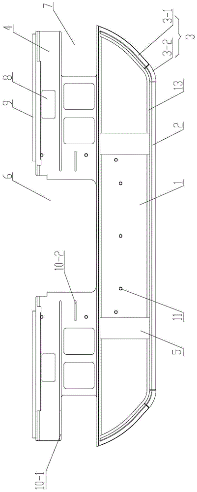
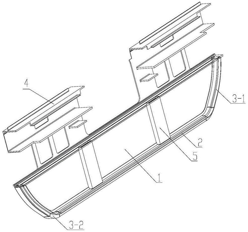
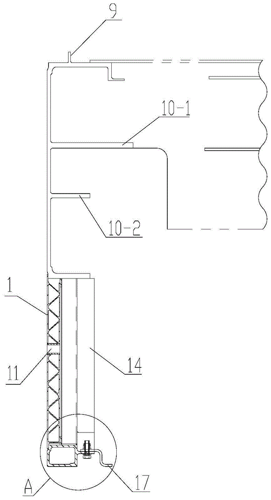
[0035] Please refer to figure 1 , figure 2 , image 3 , figure 1 It is a schematic front view of the inner side of the rail vehicle underframe end plate assembly provided by the present invention; figure 2 A perspective view of the rail vehicle underframe end plate assembly provided by the present invention; image 3 A cross-sectional view of a rail vehicle undercarriage end plate assembly provided by the present invention.

[0036] In a s...


PUM


Abstract

The invention discloses a railway vehicle chassis end plate assembly. The railway vehicle chassis end plate assembly comprises an end plate (1), a bottom beam (2), bent beams (3), buffering beams (4) and reinforcement beams (5), wherein the appearance of the end plate (1) is consistent with the appearance of the fracture of an under-vehicle movement device, the bottom beam (2) is arranged on the inner side of the lower edge of the end plate (1), the bent beams (3) are arranged on the inner sides of the two edges of the end plate (1), the buffering beams (4) are located on the end plate (1), the outer surfaces of the buffering beams (4) and the outer surface of the end plate (1) are located on the same plane, a U-shaped groove (6) used for containing a draw gear is formed between the buffering beams (4), vehicle end shock absorber installation grooves (7) and installation holes (8) for pipelines and lines to penetrate through are formed in the two sides of the buffering beams (4), and the reinforcement beams (5) are longitudinally arranged between the buffering beams (4) and the bottom beam (2). By means of the end plate assembly, the vehicle end rigidity can be improved, the vibration mode can be improved, closed space can be formed when the end plate assembly is combined with an under-vehicle movable device cabin, pipelines and devices under a vehicle can be protected, the railway vehicle chassis end plate assembly is particularly suitable for the high-speed railway vehicle. The invention further discloses the railway vehicle with the railway vehicle chassis end plate assembly.

Description

technical field [0001] The invention relates to the technical field of rail vehicles, in particular to the chassis end plates of rail vehicles. The invention also relates to a rail vehicle provided with said end plate. Background technique [0002] The shape of the movable equipment cabin under the rail vehicle is consistent with the cross section of the car body. Install the end plate, install the snow plate on the upper part of the bogie, and form the overall frame structure with the skeleton, the lower side beam of the car body, and the equipment under the car as the installation support. [0003] The utility model patent with the authorized announcement number CN 202806776U discloses an underframe partition wall and an EMU. The disclosed underframe partition wall is the end plate of the movable equipment compartment under the vehicle. The partition wall is an integrated structure, including flat plate For the support frame of the frame structure, a support plate is fix...

Claims


Application Information

Patent Timeline
Patent Type & Authority Patents(China)
IPC IPC(8): B61F1/10
CPCB61F1/10
Inventor 刘鹏飞刘延超孙现亮李吉春张永贵寇福俊林庆琳丁叁叁田爱琴梁建英
Owner CRRC QINGDAO SIFANG CO LTD
Learn More