
Depositing apparatus

A technology of evaporation and edge position, applied in vacuum evaporation plating, sputtering plating, ion implantation plating, etc., can solve the problems of reduced pattern precision and reduced adhesion

Inactive Publication Date: 2015-06-24
SAMSUNG DISPLAY CO LTD
View PDF9 Cites 12 Cited by
  • Summary
  • Abstract
  • Description
  • Claims
  • Application Information

AI Technical Summary

Problems solved by technology

[0006] However, in the case where the size of the substrate is large, warpage generated at the central portion of the mask becomes significant due to the dead weight of the substrate and the mask.
Even when pressure is applied to the entire substrate, the adhesiveness between the substrate and the mask at the edge position of the substrate decreases, thereby reducing the precision of the pattern formed on the substrate.

Method used


Image

  • Depositing apparatus
  • Depositing apparatus
  • Depositing apparatus

Examples


Embodiment Construction

[0056] The advantages and features of the present invention and their realization methods will become clearer with reference to the embodiments described later in detail with reference to the accompanying drawings. However, the present invention is not limited to the embodiments disclosed below, and can be realized in various forms different from each other. The embodiments of the present invention are only to make the disclosure of the present invention more complete, and to contribute to the common knowledge in the technical field to which the present invention belongs. It is provided by knowledgeable persons to fully convey the scope of the present invention, and the present invention is defined only by the scope described in the claims. Throughout the specification, the same reference numerals denote the same constituent elements. The sizes and relative sizes of layers and regions in the drawings may be shown exaggerated for clarity of illustration.

[0057] When it is indi...


PUM


Abstract

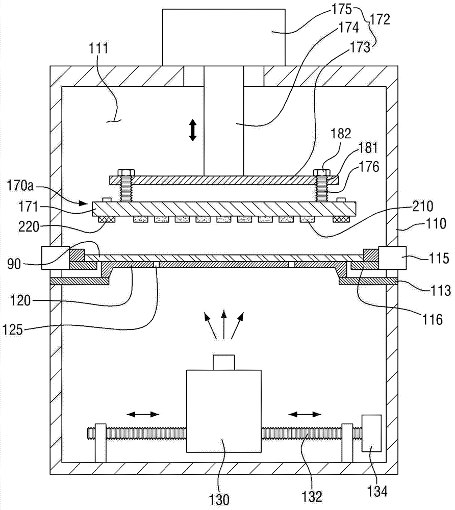
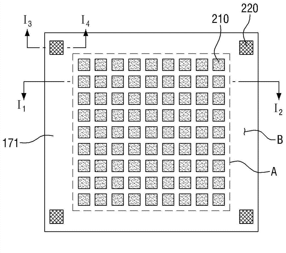
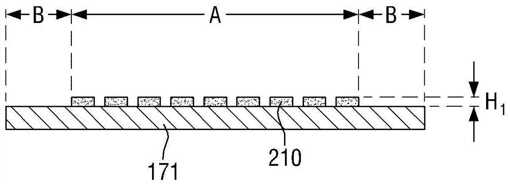
The invention discloses a depositing apparatus comprising a mask, tightly clinging unit, and a depositing source. The mask is arranged on the lower portion of a substrate and is provided with an opening pattern. The tightly clinging unit is arranged on the upper portion of the substrate and pressurizes the top surface of the substrate while facing the mask side in order that the bottom surface of the substrate tightly clings to the mask. The depositing source is arranged on the lower portion of the mask and supplying a depositing substance while facing the mask side. The tightly clinging unit comprises a pressurizing plate, a substrate pressuring component, and multiple protruded components. The pressurizing plate is disposed on the upper portion of the substrate and comprises a first area corresponding to the edge position of the substrate and a second area except the first area. The substrate pressuring component is located in the first area and protrudes toward the substrate in order to pressurize the edge position on the top surface of the substrate. The multiple protruded components are located in the second area and protrude toward the substrate.

Description

technical field [0001] The present invention relates to a vapor deposition device. Background technique [0002] Recently, as a device for solving the shortcomings of conventional display devices such as cathode ray tubes (Cathode Ray Tube), flat panel display devices (Flat Panel Display Devices) have been developed and launched. Such flat panel display devices include liquid crystal display devices (Liquid Crystal Display Device), Organic Light Emitting Diode Display Device, and Plasma Display Panel. [0003] Among them, the organic light-emitting display device not only has the advantages of thin thickness, wide viewing angle, and fast response speed, but also has the advantage of low price due to simple manufacturing process. Therefore, such an organic light emitting display device has recently attracted attention as a type of flat panel display device. [0004] On the other hand, as recent flat-panel display devices tend to be larger, organic light-emitting display dev...

Claims


Application Information

Patent Timeline
Patent Type & Authority Applications(China)
IPC IPC(8): C23C14/04C23C14/24
CPCC23C14/042H10K71/00
Inventor 俞薰
Owner SAMSUNG DISPLAY CO LTD
Learn More