
An electromagnetically driven knitting needle selection device

An electromagnetic drive, knitting needle technology, applied in knitting, weft knitting, textiles and papermaking, etc., can solve the problems of inaccurate positioning, difficult to replace, complex structure, etc., and achieve the effect of reducing costs

Inactive Publication Date: 2017-03-01
WUHAN TEXTILE UNIV
View PDF1 Cites 0 Cited by
  • Summary
  • Abstract
  • Description
  • Claims
  • Application Information

AI Technical Summary

Problems solved by technology

[0004] The purpose of the present invention is to provide an electromagnetically driven knitting needle selection device, which solves the problems of relatively small axial driving force, inaccurate positioning during high-speed knitting, and complicated structure that is difficult to replace in the prior art

Method used


Image

  • An electromagnetically driven knitting needle selection device
  • An electromagnetically driven knitting needle selection device

Examples


Embodiment Construction

[0019] The present invention will be described in detail below in conjunction with the accompanying drawings and specific embodiments.

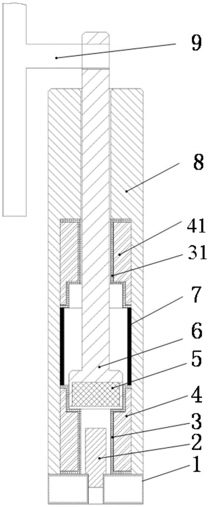
[0020] A structure of an electromagnetically driven knitting needle selection device, such as figure 1 , 2 As shown, it includes: an electromagnetic drive member 6 (including a permanent magnet 5 in the electromagnetic drive member), an upper electromagnetic coil 41 (including an upper electromagnetic coil skeleton 31), a lower electromagnetic coil 4 (including a lower electromagnetic coil skeleton 3), a silicon steel core 2. The shell 8, the base 1, the needle jack 9, the knitting needle 10 and the control system are composed.

[0021] Specifically, the shell 8 is fixed on the base 1 through threaded connection, the inner hole of the upper half of the shell 8 provides guidance for the electromagnetic drive member 6, and the lower half of the shell 8 provides installation space for the upper electromagnetic coil 41 and the lower electromagne...


PUM


Abstract

The invention discloses an electromagnetic-driven knitting needle selection device. An electromagnetic drive component is arranged in a shell. The top of the electromagnetic drive component extends out of the shell and is connected with a needle jack. A round groove is formed in the bottom of the electromagnetic drive component. An inner permanent magnet of the electromagnetic drive component is arranged in the groove. A lower electromagnetic coil framework is arranged on the inner lower portion of the shell and is in a concave platform shape. A lower electromagnetic coil is arranged between the lower electromagnetic coil framework and the shell. The concave platform surface of the lower electromagnetic coil framework is in contact with the bottom of the electromagnetic drive component. A silicon steel iron core in the shell is connected to a base. An upper electromagnetic coil framework is arranged in the shell and located above the lower electromagnetic coil framework. The lower end of the upper electromagnetic coil framework is in a concave platform shape, and an upper electromagnetic coil is arranged between the upper electromagnetic coil framework and the shell. The electromagnetic-driven knitting needle selection device solves the problems that in the prior art, axial drive force is small, locating is inaccurate in the high-speed knitting process, the structure is complex, and the electromagnetic-driven knitting needle selection device is difficult to replace.

Description

technical field [0001] The invention belongs to the technical field of textile machinery and relates to an electromagnetically driven knitting needle selection device. Background technique [0002] In the field of textile machinery, the jacquard circular knitting machine performs jacquard on the fabric to weave various patterns and patterns. The electronic needle selection devices of the existing computerized jacquard circular knitting machines are mainly electromagnetic and piezoelectric, and they all use mechanical parts such as triangular cams, jacquard sheets, and needle jacks to select needles. Therefore, there is a triangular cam in the braiding mechanism to cause impact friction and lateral force on the knitting needle. With the continuous improvement of the speed of the knitting machine, the performance requirements of the knitting needle and the triangular cam are higher. When the strength and wear resistance of the knitting needle and the triangular cam reach the ...

Claims


Application Information

Patent Timeline
Patent Type & Authority Patents(China)
IPC IPC(8): D04B15/78
CPCD04B15/78
Inventor 张弛吴晓光朱里张成俊
Owner WUHAN TEXTILE UNIV
Learn More