Magnetic circuit structure of double-row permanent magnet centripetal excitation rectangular open magnetic field type electromagnetic vibrating table with magnetic field tracking compensation

A tracking compensation, electromagnetic vibration technology, applied in vibration testing, testing of fluids using vibration, machine/structural components, etc., can solve the problems of magnetization effect limitation, difficult to guarantee magnetic field uniformity, magnetic circuit influence, etc. The effect of machining and assembly accuracy, simple and reliable magnetic circuit structure, and large air-gap magnetic induction intensity

Active Publication Date: 2016-06-08
HARBIN INST OF TECH
View PDF6 Cites 0 Cited by
  • Summary
  • Abstract
  • Description
  • Claims
  • Application Information

AI Technical Summary

Problems solved by technology

[0005] The disadvantages of the above two technical solutions are: 1) the cylindrical outer yoke needs to be processed in the long inner dimension, which is difficult to process and difficult to guarantee the accuracy; 2) when the cylindrical permanent magnet is used, the through hole needs to be processed on the permanent magnet And it is fixed on the yoke by non-magnetic bolts, the assembly is complicated and will affect the magnetic circuit; when a cylindrical permanent magnet is used, it is difficult to sinter, process, magnetize and assemble a large-sized cylindrical permanent magnet; 3) The cylindrical outer yoke needs to be set on the central yoke. If the permanent magnet is magnetized first and then assembled, the assembly is very difficult and the assembly accuracy is difficult to guarantee; the permanent magnet of AlNiCo material can be assembled first and then magnetized. However, due to the low coercive force of the permanent magnet of the AlNiCo material, the magnetization effect is limited and the performance is not good, which seriously restricts the mechanical properties and indicators of the magnetic circuit structure.
[0007] The disadvantages of this technical solution are: 1) the entire magnetic circuit structure is composed of multiple structural combinations and splicing, and the structure is complex; the small permanent magnet needs to be installed on the wedge-shaped pole piece by gluing or other methods, which is complicated to assemble and difficult to ensure. Assembly accuracy; 2) The static magnetic induction intensity at a certain position in the air gap is directly related to the working point of the permanent magnet at that position, and the uniformity of the magnetic field in the entire air gap is difficult to guarantee, and the consistency of materials and processes for small permanent magnets is required Higher; 3) The permanent magnet directly faces the air gap, and the additional magnetic field generated after the working coil is energized will force it to be magnetized or demagnetized. When a large current is passed through the working coil, it is easy to cause irreversible demagnetization of the permanent magnet; 4) When the working coil is energized, the magnetic flux on one side of the coil increases and the magnetic flux on the other side decreases. Since the permanent magnet directly faces the air gap, the magnetic circuit on the side where the magnetic flux increases is easy to saturate. At this time, one side of the coil increases The magnetic flux of the coil is less than the reduced flux of the other side, resulting in a decrease in the average magnetic induction intensity at the position of the coil, which in turn distorts the generated standard vibration signal
However, there are various problems and deficiencies in the existing technologies. It is difficult to further improve the uniformity of the static magnetic induction intensity distribution in the air gap and the linearity index of the output electromagnetic driving force after the coil is energized.
[0009] There are three key issues: (1) The uniformity of the magnetic induction intensity distribution of the main magnetic circuit in the long air gap is difficult to guarantee
Before the coil is energized, the permanent magnet is excited to form the magnetic induction intensity distribution of the main magnetic circuit. With the increase of the stroke of the electromagnetic vibrating table, the non-uniformity of the magnetic field in the long air gap is very prominent, which seriously restricts the linearity of the output electromagnetic driving force after the coil is energized. Some researchers try to compensate by adjusting the current waveform, but the effect is difficult to guarantee, especially for the high-order magnetic field non-uniformity error compensation effect is poor, so far no truly effective and highly practical compensation method has been proposed at home and abroad
(2) The influence of the armature reaction after the working coil is energized
(3) It is difficult to process and assemble long yokes and large-size permanent magnets, and the accuracy is difficult to guarantee
[0011] In summary, restricted by the above problems, the standard low-frequency vibration produced by existing technical solutions is difficult to make breakthroughs in indicators such as waveform distortion, and it is difficult to meet the high-precision calibration of low-frequency / ultra-low-frequency vibration, especially the next generation with very low frequency and the need for vibration calibration of ultra-precise features

Method used


Image

  • Magnetic circuit structure of double-row permanent magnet centripetal excitation rectangular open magnetic field type electromagnetic vibrating table with magnetic field tracking compensation
  • Magnetic circuit structure of double-row permanent magnet centripetal excitation rectangular open magnetic field type electromagnetic vibrating table with magnetic field tracking compensation
  • Magnetic circuit structure of double-row permanent magnet centripetal excitation rectangular open magnetic field type electromagnetic vibrating table with magnetic field tracking compensation

Examples


Embodiment Construction

[0031] The specific implementation manner of the present invention will be described in detail below with reference to the accompanying drawings, and examples will be given.

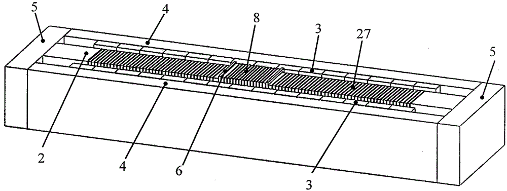
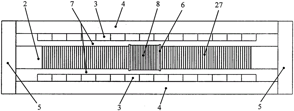
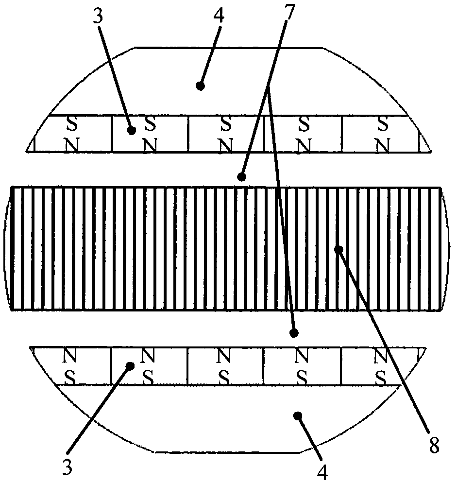
[0032] A magnetic circuit structure of a double-row permanent magnet centripetal excitation rectangular open magnetic field type electromagnetic vibrating table with magnetic field tracking compensation, consisting of a central yoke 2, a permanent magnet 3, an outer yoke 4, an end yoke 5, a coil bobbin 6 and a working coil 8, the overall structure is axisymmetric. The cross-sections of the central yoke 2, permanent magnet 3, outer yoke 4, and end yoke 5 are all rectangular. The cross-section of the coil bobbin 6 is square-shaped. The ends are respectively rigidly connected with the two end yokes 5 to form a zigzag yoke structure. The central yoke 2 is installed on the long axis of the zigzag yoke structure, and the two ends are respectively rigidly connected with the two end yokes 5. The permanent magnet ...


PUM


Abstract

Provided is a magnetic circuit structure for a rectangular open-type magnetic field of an electromagnetic shaking table by adopting double rows of permanent magnets with centripetal excitation for tracking and compensation of the magnetic field, pertaining to the technical field of vibration and measurement. Provided is structural design of the rectangular open-type magnetic field. The double rows of permanent magnets are symmetrically arranged at insides of long magnet yokes with same magnetic poles oppositely arranged. By means of magnet yokes, a symmetrical closed magnetic circuit is formed. Magnetic inductive intensity distribution with high evenness is generated in an air gap. Compensating coils are arranged on a central magnet yoke. Galvanized electric current is opposite to electric current of working coils in direction and proportionate to phase synchronous tracking and amplitude. A formed compensating magnetic field is used for tracking and compensating for influence of armature reaction. Considerations are taken into large stroke, uniformity of a high magnetic field, high thrust and features of linear electromagnetic driving force so that a technical scheme, with high precision and large stroke, of the magnetic circuit structure of the electromagnetic shaking table is provided for low frequency / ultra-low frequency vibration calibration.

Description

technical field [0001] The invention belongs to the technical field of vibration measurement, and mainly relates to a magnetic circuit structure of a double-row permanent magnet centripetal excitation rectangular open magnetic field type electromagnetic vibrating table for magnetic field tracking compensation. Background technique [0002] In recent years, aerospace, building bridges, earthquake prevention and disaster reduction and other fields have raised the need for low-frequency / ultra-low-frequency vibration calibration. The electromagnetic vibrating table that generates standard vibration signals is the key equipment for high-precision vibration calibration. In order to improve the signal-to-noise ratio of the standard vibration signal and ensure the calibration accuracy of low-frequency / ultra-low-frequency vibration, the electromagnetic vibration table is required to have as large a stroke as possible under the premise of ensuring thrust and precision. In the design ...

Claims


Application Information

Patent Timeline
Patent Type & Authority Patents(China)
IPC IPC(8): B06B1/04G01M7/02
Inventor 谭久彬何张强崔俊宁
Owner HARBIN INST OF TECH
Why Eureka
Try Eureka