Regulating and controlling device for changing stationary position of flow field and application of regulating and controlling device

A control device and stagnation point technology, applied in the direction of streamlined body, transportation and packaging, aerodynamic improvement, etc., can solve the problems of increased surface resistance, increased resistance, and destruction of aerodynamic shape, etc., to achieve large electromagnetic driving force and tightness Good, fast response effect

Active Publication Date: 2019-10-08
ZHEJIANG UNIV
View PDF15 Cites 0 Cited by
  • Summary
  • Abstract
  • Description
  • Claims
  • Application Information

AI Technical Summary

Problems solved by technology

[0003] The traditional zero-mass jet process includes the process of "breathing" and "breathing out". During the research on the surface drag reduction of the existing synthetic jet actuator placed on the front of the car, it was found that when the synthetic jet injector is in the process of "breathing out", the The formed aerodynamic shape effectively reduces the surface resistance of the car, but when the synthetic jet is in the process of "breathing", the surface resistance of the car increases instead, mainly because the actuator is not "inhaling" during the actual process of "breathing". Inhale the fluid around the outlet, but “inhale” the gas in the vortex pair formed by the previous “exhale”, destroying the aerodynamic shape formed by the previous “exhale”, thus increasing the resistance

Method used


Image

  • Regulating and controlling device for changing stationary position of flow field and application of regulating and controlling device
  • Regulating and controlling device for changing stationary position of flow field and application of regulating and controlling device
  • Regulating and controlling device for changing stationary position of flow field and application of regulating and controlling device

Examples


Embodiment Construction

[0019] The technical solution of the present invention will be further described in detail below in conjunction with the accompanying drawings.

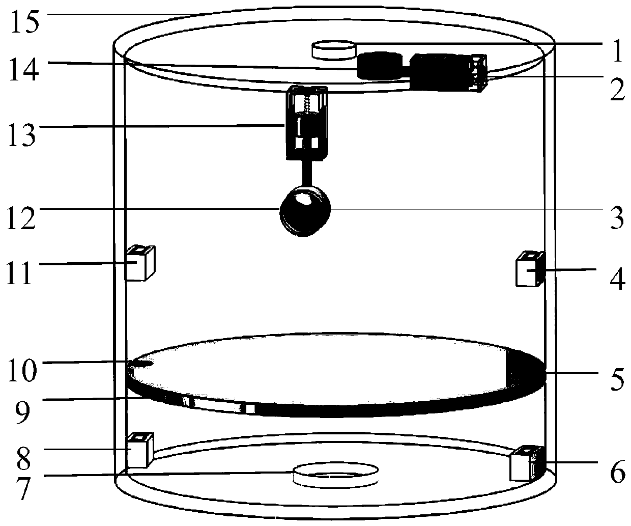
[0020] Such as figure 1 As shown, it is a structural schematic diagram of a control device for changing the stagnation point position of the flow field according to the present invention. The control device mainly includes: a first proportional electromagnet 2, a second plug 3, a first electromagnet A 4, Armature A 5, second electromagnet A6, second electromagnet B 8, rubber piston 9, armature B 10, second electromagnet B 11, second proportional electromagnet 13, first plug 14, housing 15.

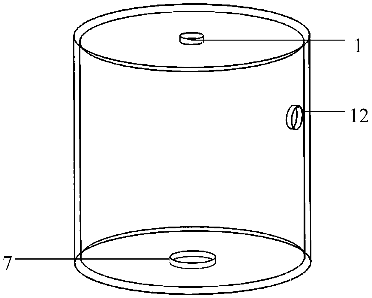
[0021] Such as figure 2 As shown, the housing 15 is cylindrical with a top surface and a bottom surface, a jet port 1 is opened on the top surface, and at least one opening 12 is provided on the side wall of the housing 15, figure 2 In the example shown, only one opening 12 is provided. In order to ensure air pressure balance in the housing ...


PUM


Abstract

The invention discloses a regulating and controlling device for changing the stationary position of a flow field and an application of the regulating and controlling device. The regulating and controlling device comprises a shell, two groups of electromagnet groups, a rubber piston, a plurality of proportional electromagnets and a plurality of plugs; a jet opening is formed in the top surface of the shell, at least one opening is formed in the side wall of the shell, the two groups of electromagnet groups are fixedly arranged on the inner side wall of the shell in a one-to-one manner, the rubber piston is arranged between the two groups of electromagnet groups, and the corresponding plugs are controlled by the proportional electromagnets to stretch and contract so as to control the openingsize of the jet opening or the opening; and a pulse type current control is carried out in the two groups of electromagnet groups and the proportional electromagnets, so that the rubber piston is inthe rising process, the jet opening is opened, the opening is closed, in the descending process, the jet opening is closed, and the opening is opened. Finally, it is guaranteed that the jet opening isonly subjected to outwards 'air injection' at the position and not inwards 'air suction'. The regulating and controlling device is simple in structure, the position of the parking point in the automobile flow field can be changed by the virtual pneumatic appearance formed at the jet opening, so that the pressure on the wall surface of the automobile can be effectively reduced.

Description

technical field [0001] The invention belongs to the technical field of jet control, and in particular relates to a control device for changing the stagnation point position of a flow field and its application. Background technique [0002] Zero-mass jet technology, also known as synthetic jet technology, is a popular active flow control method in modern fluid mechanics. It has a wide range of applications in the fields of reducing aircraft surface resistance, improving aircraft wing aerodynamic characteristics, suppressing noise, and controlling flow separation. Application prospect. As the core equipment of zero-mass jet, synthetic jets are mainly divided into piston vibration type, acoustic excitation type, shape memory alloy actuation type, polyvinylidene fluoride film vibration type, and piezoelectric film vibration type according to different excitation methods. Although the piston vibration type can provide a large jet flow, it needs an additional mechanical transmiss...

Claims


Application Information

Patent Timeline
Patent Type & Authority Applications(China)
IPC IPC(8): B62D35/00
CPCB62D35/00B62D35/005Y02T10/82
Inventor 宋小文高宇张鸣晓戚昱宸詹文超言森博
Owner ZHEJIANG UNIV
Why Eureka
Try Eureka