
Air-conditioner control method and device

A control method and control device technology, which is applied in the field of air conditioning, can solve problems such as system load instability, achieve the effects of reducing system energy consumption, stabilizing load, and solving system load instability

Active Publication Date: 2015-06-24
GREE ELECTRIC APPLIANCES INC
View PDF5 Cites 15 Cited by
  • Summary
  • Abstract
  • Description
  • Claims
  • Application Information

AI Technical Summary

Problems solved by technology

[0007] The embodiment of the present invention provides an air conditioning control method and device to at least solve the technical problem of unstable system load caused by variable water temperature or flow control air conditioning in the prior art

Method used


Image

  • Air-conditioner control method and device
  • Air-conditioner control method and device
  • Air-conditioner control method and device

Examples


Embodiment 1

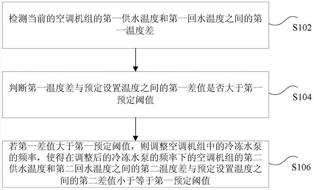
[0032] According to an embodiment of the present invention, an air conditioner control method is provided, such as figure 1 As shown, the air conditioning control method in this embodiment includes:

[0033] S102, detecting the first temperature difference between the first supply water temperature and the first return water temperature of the current air conditioning unit;

[0034] Optionally, in this embodiment, the air-conditioning control method can be applied to the refrigeration side of the cold source system, but not limited to, to detect the first water supply temperature T of the refrigeration main pipe of the current air-conditioning unit 供1 and the first return water temperature T 回1 The first temperature difference △T 1 .

[0035] Optionally, the detection manner in this embodiment includes at least one of the following: real-time detection, performing detection every predetermined period.

[0036] For example, taking the air conditioner unit A as an example, e...

Embodiment 2

[0076] According to an embodiment of the present invention, an air conditioner control device for implementing the above air conditioner control method is also provided, such as Figure 5 As shown, the air conditioning control device in this embodiment includes:

[0077] 1) The first detection unit 502 is used to detect the first temperature difference between the first supply water temperature and the first return water temperature of the current air conditioning unit;

[0078] Optionally, in this embodiment, the air-conditioning control method can be applied to the refrigeration side of the cold source system, but not limited to, to detect the first water supply temperature T of the refrigeration main pipe of the current air-conditioning unit 供1 and the first return water temperature T 回1 The first temperature difference △T 1 .

[0079] Optionally, the detection manner in this embodiment includes at least one of the following: real-time detection, performing detection eve...


PUM


Abstract

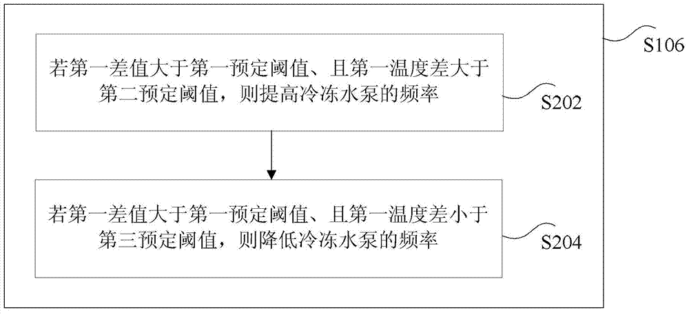
The invention discloses an air-conditioner control method and device. The air-conditioner control method includes steps of detecting a first temperature difference between a first water supply temperature and a first water return temperature of the air conditioning unit; judging whether a first difference between the first temperature difference and a preset temperature is larger than a first preset threshold or not; if the first difference is larger than the first preset threshold, adjusting frequency of a freezing water pump in the air conditioning unit, so that a second difference between a second temperature difference between a second water supply temperature and a second water return temperature of the air conditioning unit and the preset temperature is smaller than or equal to the first preset threshold under the adjusted frequency of the freezing water pump. The air-conditioner control method solves the technical problem of instable system load caused by variable water temperature or flow control of the air conditioners in the prior art and has the technical advantages that system load stability is maintained, refrigeration and moisturizing of the tail end of the air conditions are guaranteed and system energy consumption is lowered.

Description

technical field [0001] The present invention relates to the field of air conditioners, in particular to an air conditioner control method and device. Background technique [0002] The traditional HVAC group control system usually adjusts the load of the HVAC system by detecting parameters such as the temperature or pressure difference of the chilled water supply and return main pipe. When the air conditioning system is a primary variable flow system, the general unilateral variable flow system Variable flow control, little consideration is given to water temperature control of variable flow systems; [0003] When the variable flow control is adopted, if the frequency of the refrigerated variable frequency water pump is reduced, its power will be greatly reduced. After the flow of refrigerated water is reduced, the cooling capacity of the unit will decrease, and the power will also decrease. The COP (Coefficient of Performance, energy consumption ratio of the unit) )Almost u...

Claims


Application Information

Patent Timeline
Patent Type & Authority Applications(China)
IPC IPC(8): F24F11/00
CPCF24F11/30F24F11/89F24F2110/00F24F2140/20
Inventor 姜春苗何玉雪周获宋海川
Owner GREE ELECTRIC APPLIANCES INC
Learn More