Eureka AIR delivers breakthrough ideas for toughest innovation challenges, trusted by R&D personnel around the world.

Light-gas gun pneumatic separation sabot

A pneumatic separation and light gas cannon technology, which is applied in the direction of projectiles, offensive equipment, weapon types, etc., can solve problems such as poor separation effect, difficult separation of bomb holders, and complex structure of the light gas cannon system, so as to reduce negative weight and intensify Separate, versatile effects

Active Publication Date: 2015-06-24
NORTHWEST INST OF NUCLEAR TECH
View PDF4 Cites 33 Cited by
  • Summary
  • Abstract
  • Description
  • Claims
  • Application Information

AI Technical Summary

Problems solved by technology

[0003] In order to solve the technical problems of the separation difficulty of the existing light gas gun bullet holder, which needs to be separated by means of other mechanical devices and the separation effect is poor, and the structure of the light gas gun system is complicated, the invention provides a pneumatically separated bullet holder, which can During the process of hitting the target, the automatic separation of the bullet holder and the projectile can be smoothly realized

Method used


Image

  • Light-gas gun pneumatic separation sabot
  • Light-gas gun pneumatic separation sabot
  • Light-gas gun pneumatic separation sabot

Examples


Embodiment 1

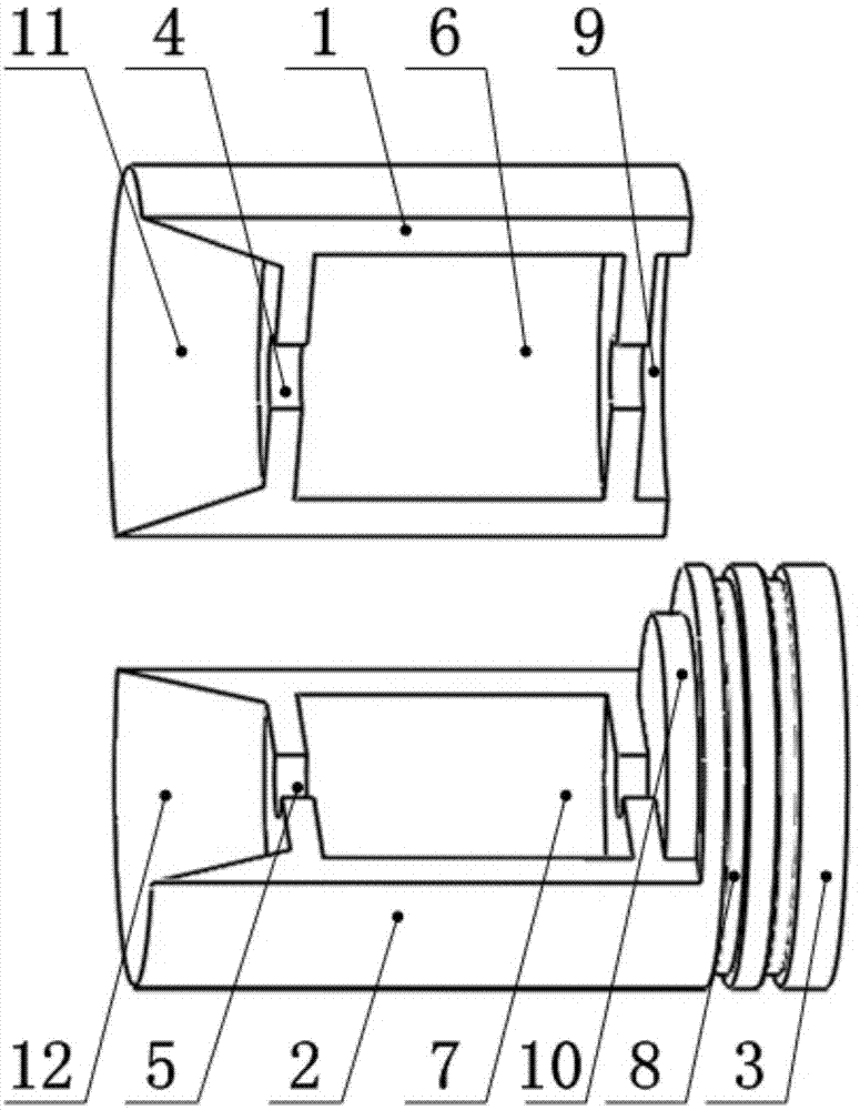
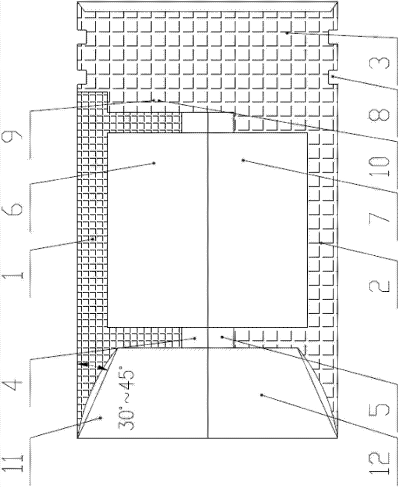
[0032] Embodiment one: (see figure 1 , figure 2 ) The present embodiment is made up of upper support valve 1, lower support valve 2 and base plate 3; upper support valve 1 and lower support valve 2 are two corresponding half cylinders, and the front end of upper support valve 1 is designed with air vortex structure 11, and the center There are projectile holes 4; the lower support valve 2 and the base plate 3 form an integral body, the base plate is necessary in the present invention, and plays the role of transmitting high-pressure gas pressure, and the front end of the lower support valve 2 is designed with a gas valve corresponding to the upper support valve 1 The vortex structure 12 has a projectile hole 5 in the center; the bottom plate 3 is engraved with two sealing grooves 8 . The upper half of the projectile hole 4 of the upper support valve 1 corresponds to the lower half of the projectile hole 5 of the lower support valve 2, and the semicircular gap 9 of the upper ...

Embodiment 2

[0033] Embodiment two: (see figure 2 ) The difference between this embodiment and the previous embodiment is that the construction lines of the air vortex structure 11 and the air vortex structure 12 can be straight lines or arcs. The angle between the straight line and the outer wall of the support valve is 30°-45°; the arc is tangent to the outer wall of the support valve, and the angle between the chord and the outer wall of the support valve is 30°-45°.

Embodiment 3

[0034] Embodiment three: (see figure 1 , figure 2 ) The difference between the third embodiment and the first embodiment is that the middle of the upper support valve 1 is hollowed out into a hollow structure 6 , and the middle of the lower support valve 2 is hollowed out into a hollow structure 7 corresponding to the upper support valve 1 .


PUM


Abstract

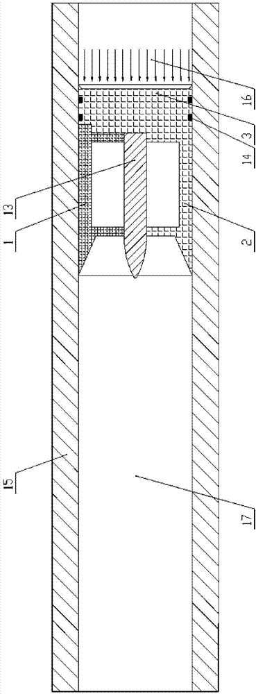
The invention relates to a light-gas gun pneumatic separation sabot, and aims at solving the problems that for an existing sabot, an additional device is needed to conduct separation on the sabot, the effect is not ideal and the cost is increased. The light-gas gun pneumatic separation sabot is composed of an upper supporting disc, a lower supporting disc and a base plate; the upper supporting disc and the lower supporting disc are two corresponding semi-cylinders. An upper half bullet hole is formed in the center of the upper supporting disc, and the middle of the upper half bullet hole is hollowed out to be of a hollow structure; the lower supporting disc and the base plate are formed to be a whole, a lower half bullet hole is formed in the center of the lower supporting disc, and the middle of the lower half bullet hole is hollowed out to be of the hollow structure; two seal grooves are carved on the base plate. The upper half bullet hole of the upper supporting disc corresponds to the lower half bullet hole of the lower supporting disc, a semicircle notch of the upper supporting disc is engaged with a boss of the lower supporting disc, under the condition of not adding a separating device, automatic separation of the sabot and a bullet is achieved through air resistance in a target chamber, and the light-gas gun pneumatic separation sabot has the advantages of improving the external ballistic property of the bullet and reducing the firing cost.

Description

technical field [0001] The invention belongs to the field of explosion and impact dynamics, and in particular relates to an improvement of a light gas projectile support structure. Background technique [0002] The role of the bullet rest is to center and guide the projectile in the barrel, transmit high-pressure gas pressure, make the projectile obtain a higher initial velocity, and separate from the projectile during the process from exiting the muzzle to hitting the target, so that it has good external ballistic performance , in order to avoid further loading of the kinetic energy of the bullet rest on the projectile. The existing method mainly adopts an additional separation device for separation. The main problems of this technology are: the additional separation method is to install a mechanical device between the gun barrel and the target chamber, and the bullet holder is broken and separated by impact. The fragments formed after separation will still follow up and a...

Claims


Application Information

Patent Timeline
Patent Type & Authority Applications(China)
IPC IPC(8): F42B10/00
Inventor 戴湘晖初哲王可慧古仁红段建胡玉涛田亚军李虎伟
Owner NORTHWEST INST OF NUCLEAR TECH
Why Eureka
Eureka Blog
Learn More