Supersonic wind tunnel velocity field calibration and measurement total pressure tube vibration suppression device

A total pressure exhaust pipe and vibration suppression technology, which is applied in the field of wind tunnels, can solve the problems of severe total pressure exhaust pipe vibration, deformation of connecting rods, and impact on test accuracy, and achieve the effects of suppressing vibration, enhancing stiffness, and improving test accuracy

Active Publication Date: 2015-06-24
CHINA ACAD OF AEROSPACE AERODYNAMICS
View PDF5 Cites 5 Cited by
  • Summary
  • Abstract
  • Description
  • Claims
  • Application Information

AI Technical Summary

Problems solved by technology

When the wind tunnel is started, because the total pressure exhaust pipe is impacted by the air flow, the total pressure exhaust pipe shakes violently, and the connecting rods will be deformed at the matching part of the angle of attack mechanism. In severe cases, the bent frame cannot move forward and backward, and the test cannot be carried out; When the flow field is stable, the vibration of the total pressure exhaust pipe will also affect the test accuracy; the total pressure exhaust pipe is shaken violently by the impact of the air flow, and the connecting rod is affected by the bending moment
With the forward movement of the total pressure bent frame, the bending moment on the connecting rod also increases correspondingly. When it is severe, the connecting rod will be damaged, affecting the test accuracy and causing damage to the test equipment, etc.
[0005] Due to the above difficulties, before the present invention, there was no mature method to suppress the vibration of the total pressure exhaust pipe when the supersonic wind tunnel flow field was started and stabilized.

Method used


Image

  • Supersonic wind tunnel velocity field calibration and measurement total pressure tube vibration suppression device
  • Supersonic wind tunnel velocity field calibration and measurement total pressure tube vibration suppression device
  • Supersonic wind tunnel velocity field calibration and measurement total pressure tube vibration suppression device

Examples


Embodiment Construction

[0027] In order to make the above objects, features and advantages of the present invention more comprehensible, specific implementations of the present invention will be described in detail below in conjunction with the accompanying drawings.

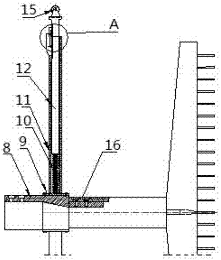
[0028] see image 3 , Figure 4 and Figure 5 , the present invention provides a vibration suppression device for calibrating the velocity field of a supersonic wind tunnel to measure the total pressure exhaust pipe, comprising: a connecting seat 9, which has an axis, and the connecting seat has two connections distributed on the axis Ends 8, 16; a support mechanism, which includes a support sleeve 11, a support rod 12 and a first elastic member 10, wherein one end of the support sleeve is connected to the connecting seat, and the other end has an opening, and the support rod Sleeved in the support sleeve, and the free end of the support rod protrudes from the opening, the first elastic member is arranged inside the support sleeve to...


PUM


Abstract

The invention discloses a supersonic wind tunnel velocity field calibration and measurement total pressure tube vibration suppression device comprising a connecting seat and four supporting mechanisms. The connecting seat is provided with a first axis and comprises two connecting ends distributed on the axis; the supporting mechanisms comprise supporting sleeves, supporting rods and first elastic components; one ends of the supporting sleeves are connected to the connecting seat, the other ends are provided with openings, the supporting rods are sleeved with the supporting sleeves, the free ends of the supporting rods extend out of the openings, and the first elastic components are arranged in the supporting sleeves and provide the applied force which is parallel to the length of the supporting sleeves and which orient to the outer sides of the supporting sleeves; the supporting mechanisms are arranged on the connecting seat and are distributed in a radiating manner corresponding to the axis. The vibration of the total pressure tube can be suppressed effectively, the rigidity of a total pressure tube test system is improved, and the testing accuracy is improved.

Description

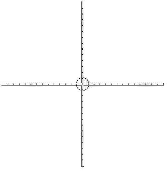
technical field [0001] The invention relates to the technical field of wind tunnels, in particular to a vibration suppressing device for supersonic wind tunnel velocity field calibration and measurement of total pressure exhaust pipes, which can effectively suppress the vibration of total pressure exhaust pipes and improve test accuracy when used for supersonic wind tunnel velocity field calibration and measurement And improve the stiffness of the test device. Background technique [0002] When the supersonic wind tunnel is debugging the velocity field, since the disturbance in the supersonic flow field propagates backward in the Mach cone, the calibration of the supersonic velocity field requires the calibration of the Mach number of the section. The calibration of the supersonic Mach number is carried out by the total pressure exhaust pipe, and the total pressure exhaust pipe is mostly in the shape of a "ten". [0003] When calibrating the velocity field in a supersonic w...

Claims


Application Information

Patent Timeline
IPC IPC(8): G01M9/04
Inventor 魏忠武董金刚彭程
Owner CHINA ACAD OF AEROSPACE AERODYNAMICS
Why Eureka
Try Eureka