
Calibration device and system of split core type current transformer

A technology for current transformers and calibration devices, which is applied to measuring devices, instruments, and measuring electrical variables, etc., to achieve the effects of avoiding on-site errors, improving accuracy, and reducing errors

Active Publication Date: 2015-06-24
STATE GRID CORP OF CHINA +1
View PDF7 Cites 0 Cited by
  • Summary
  • Abstract
  • Description
  • Claims
  • Application Information

AI Technical Summary

Problems solved by technology

[0009] The main purpose of the present invention is to provide a calibrating device and system for a clamp-on current transformer, so as to solve the problem that the calibrator of the electric energy meter in the prior art is prone to large errors

Method used


Image

  • Calibration device and system of split core type current transformer
  • Calibration device and system of split core type current transformer
  • Calibration device and system of split core type current transformer

Examples


Embodiment Construction

[0027] It should be noted that, in the case of no conflict, the embodiments in the present application and the features in the embodiments can be combined with each other. The present invention will be described in detail below with reference to the accompanying drawings and examples.

[0028] The embodiment of the present invention provides a verification device for a clamp current transformer. The verification device for a clamp current transformer provided in the embodiment of the present invention is specifically introduced as follows:

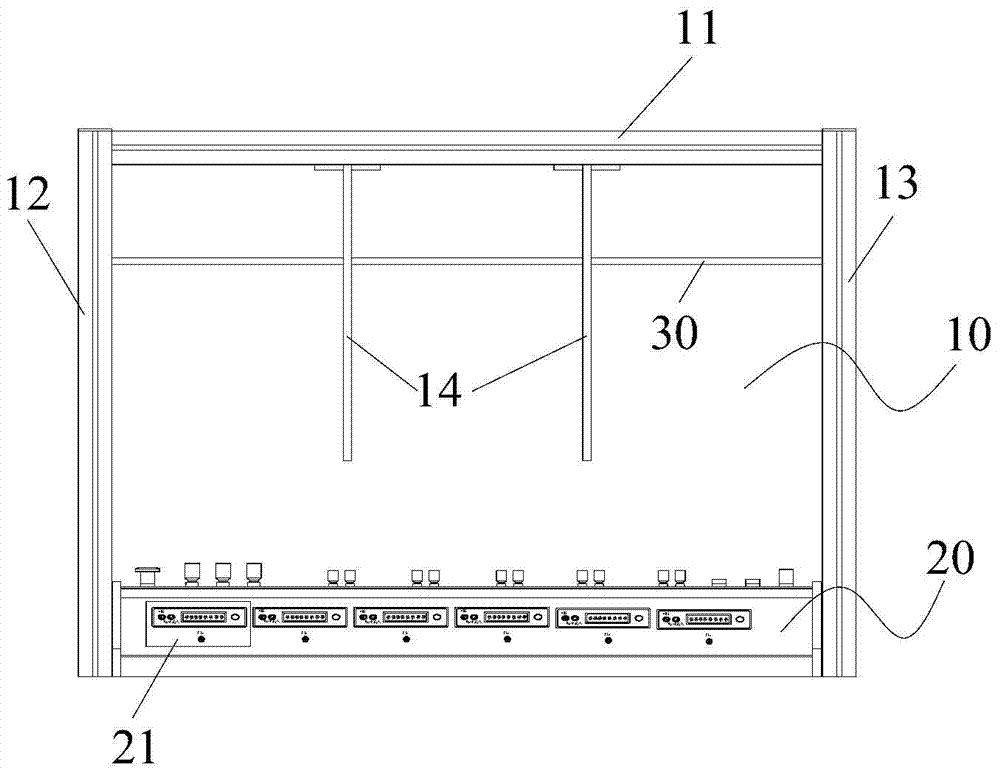
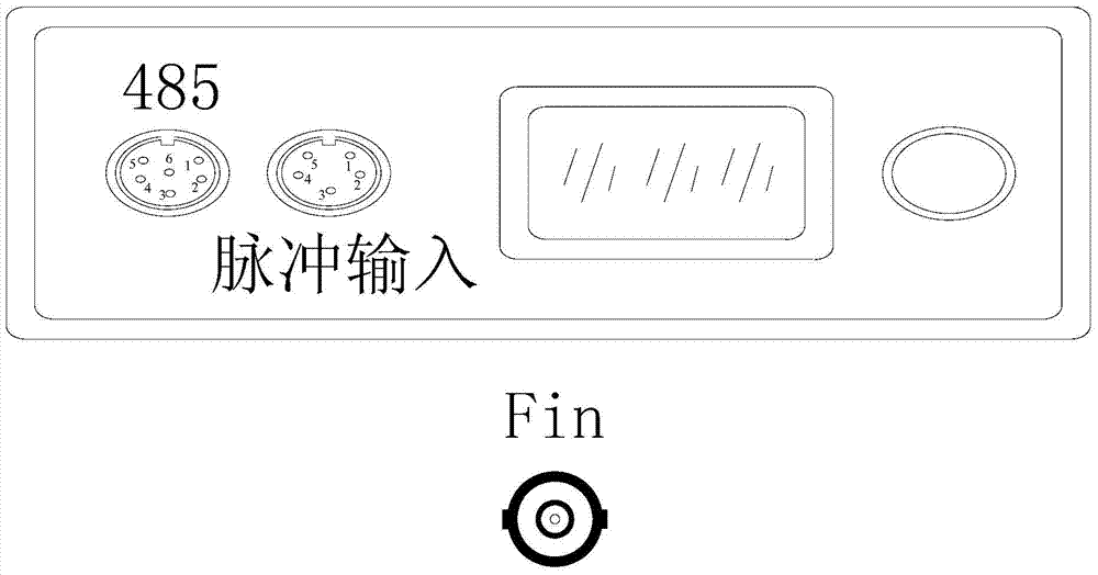
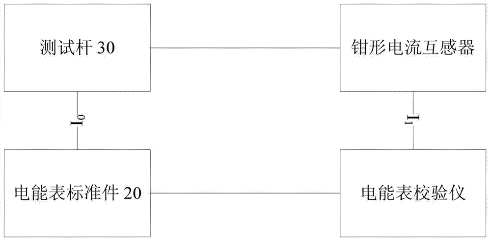
[0029] figure 1 is a structural diagram of a calibration device for a clamp current transformer according to an embodiment of the present invention, figure 2 yes figure 1 The enlarged picture of 21 places in the middle, such as figure 1 with figure 2 As shown, the verification device mainly includes a suspension frame 10, an electric energy meter standard part 20, a test rod 30 and an electric energy meter calibrator (not shown in th...


PUM


Abstract

The invention discloses a calibration device and system of a split core type current transformer. The calibration device of the split core type current transformer comprises a hanging rack, electric energy meter standard parts, testing rods and an electric energy meter calibration instrument, wherein the hanging rack is provided with a cross rod, a first supporting part, a second supporting part and fixing parts, the electric energy meter standard parts are used for providing stable testing current, the testing rods penetrate through the first supporting part, the second supporting part and the fixing parts, the two ends of each testing rod are both connected with the energy meter standard parts to form a testing loop for transmitting testing current, and the electric energy meter calibration instrument is connected with the electric energy meter standard parts and the split core type current transformer and is used for calculating and measuring electric energy amount according to the testing current detected by the split core type current transformer and feeding back the electric energy amount to the electric energy meter standard part. By means of the calibration device and system, the problem of larger errors easily produced by an electric energy meter calibration instrument in the prior art is solved, and further the effects of decreasing errors of the electric energy meter calibration instrument and improving field calibration accuracy are achieved.

Description

technical field [0001] The invention relates to the field of electric equipment, in particular to a calibration device and system for a clamp current transformer. Background technique [0002] The field calibrator of the electric energy meter is a metering device used for on-site testing of the error of the electric energy meter at the actual operating place of the installed electric energy meter such as the substation and the residential user. In the field, the electric energy meter is in the power-on operation state. Due to various factors such as customer needs and test safety, it is often not possible to disconnect the electric energy meter line, and then connect the electric energy meter field calibrator to the line to check the error of the electric energy meter. Measurement. At this time, the method adopted is to use a clamp current transformer (also known as a current clamp meter) for current sampling, by placing the current wire into the jaw of the current clamp me...

Claims


Application Information

Patent Timeline
IPC IPC(8): G01R35/00G01R35/02G01R35/04
Inventor 靳阳赵成李之彧陈旭
Owner STATE GRID CORP OF CHINA
Learn More