Vibration damping device

A technology for vibration isolation and mounting components, which is applied in vibration suppression adjustment, non-rotational vibration suppression, spring/shock absorber manufacturing, etc. It can solve the problems of the second rubber elastic body falling off, reduce the dynamic stiffness constant, prevent separation, Effect of Soft Stiffness Properties

Active Publication Date: 2015-06-24
SUMITOMO RIKO CO LTD
View PDF6 Cites 8 Cited by
  • Summary
  • Abstract
  • Description
  • Claims
  • Application Information

AI Technical Summary

Problems solved by technology

However, in this case, for example, the outer peripheral surface of the cylindrical portion is supported in a non-fixed manner by being pressed against the inner peripheral surfaces of the first rubber elastic body and the second rubber elastic body. When the contact pressure of the elastic body and the second rubber elastic body with respect to the cylindrical part is set to be small, the cylindrical part may dislodge from the first rubber elastic body, the first rubber elastic body, and 2 The rubber elastic body falls off

Method used


Image

  • Vibration damping device
  • Vibration damping device
  • Vibration damping device

Examples


Embodiment Construction

[0053] Hereinafter, embodiments of the present invention will be described with reference to the drawings.

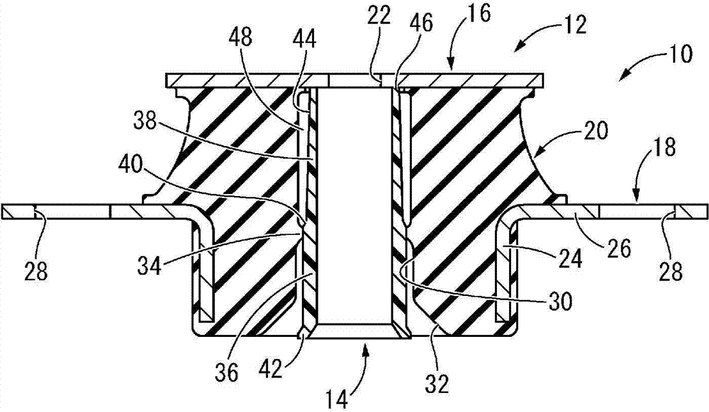
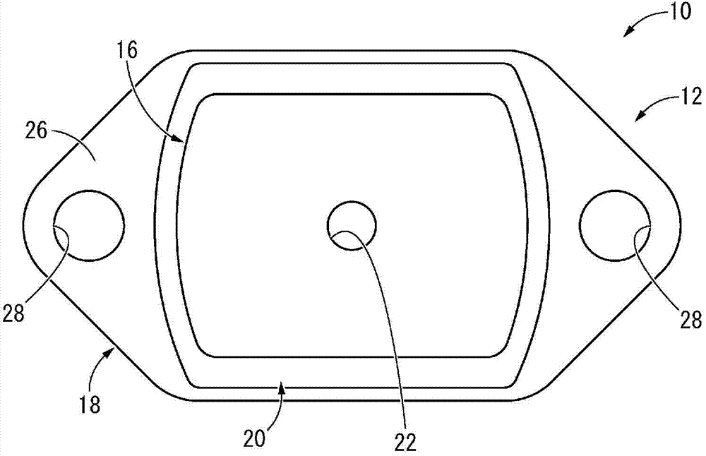
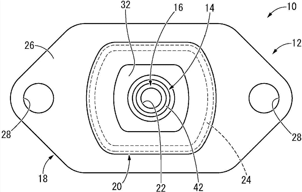
[0054] exist Figure 1 ~ Figure 3 In the figure, the engine mount 10 for automobiles is shown as the first embodiment of the vibration isolating device configured according to the present invention. This engine mount 10 has a structure in which an independent sleeve 14 is assembled on a mount main body 12, and the mount main body 12 has a structure in which a first mounting member 16 and a second mounting member 18 are elastically connected by a main body rubber elastic body 20. . In addition, in the following description, the up-and-down direction refers to the axis direction in principle. figure 1 in the up and down direction. also, figure 1 The upper side of the middle is set as the insertion top end side of the independent sleeve 14, figure 1 The lower side of the center is defined as the insertion base end side of the independent sleeve 14 .

[0055] In mo...


PUM


Abstract

Provided is a vibration damping device having a novel structure, the vibration damping device being configured so that a separate sleeve is held by a main rubber elastic body before the vibration damping device is mounted to a member to which the vibration damping device is to be connected in a vibration damping manner, and so that the vibration damping device has soft spring characteristics obtained by preventing the main rubber elastic body from having high dynamic spring characteristics in a state in which the vibration damping device is mounted to the member. A vibration damping device (10) is configured in such a manner that a first mounting member (16) and a second mounting member (18) are secured to a cylindrical main rubber elastic body (20) and in such a manner that an axial load acts between the first mounting member (16) and the second mounting member (18) while the vibration damping device (10) is in a mounted state. A separate sleeve (14) is inserted and disposed in the main rubber elastic body (20) in a non-secured manner. A rubber-side contact section (34) which is provided on the inner peripheral surface of the main rubber elastic body (20) and a sleeve-side contact section (36) which is provided on the outer peripheral surface of the separate sleeve (14) are pressed against each other, and as a result, the separate sleeve (14) is held by the main rubber elastic body (20). In the mounted state, the rubber-side contact section (34) and the sleeve-side contact section (36) are axially displaced relative to each other, and as a result, a retaining force acting between the main rubber elastic body (20) and the separate sleeve (14) is reduced.

Description

technical field [0001] The present invention relates to a vibration isolation device applied to an automobile engine mount and the like. Background technique [0002] Conventionally, there is known a vibration-isolating device that is installed between members to be connected to vibration-isolation and connects these members to each other through vibration-isolation. For example, as disclosed in Japanese Unexamined Patent Application Publication No. 2002-235784 (Patent Document 1), the vibration isolator has a structure in which a second An installation member, and a second installation member is fixed on the outer peripheral surface of the main body rubber elastic body, and the first installation member and the second installation member are elastically connected by the main body rubber elastic body. Then, the first mounting member is mounted on one of the vibration-isolating connection target members such as the power unit by using the mounting rod that penetrates the mai...

Claims


Application Information

Patent Timeline
Patent Type & Authority Applications(China)
IPC IPC(8): F16F15/08
CPCF16F1/3876F16F1/3842F16F2226/041F16F15/085
Inventor 铃木知见
Owner SUMITOMO RIKO CO LTD
Why Eureka
Try Eureka