Heating device operated with liquid fuel

A technology for heating equipment and liquid fuel, applied in lighting and heating equipment, heating/cooling equipment, liquid fuel supply/distribution, etc. The effect of volume

Active Publication Date: 2015-06-24
斯飞乐有限责任公司
View PDF5 Cites 4 Cited by
  • Summary
  • Abstract
  • Description
  • Claims
  • Application Information

AI Technical Summary

Problems solved by technology

In addition, a pre-delivery pump is used locally, which also raises the level of descending pressure in the suction duct
[0019] The disadvantage o

Method used


Image

  • Heating device operated with liquid fuel
  • Heating device operated with liquid fuel

Examples


Embodiment Construction

[0034] In said figures, the same parts and components are denoted by the same reference numerals.

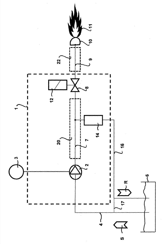
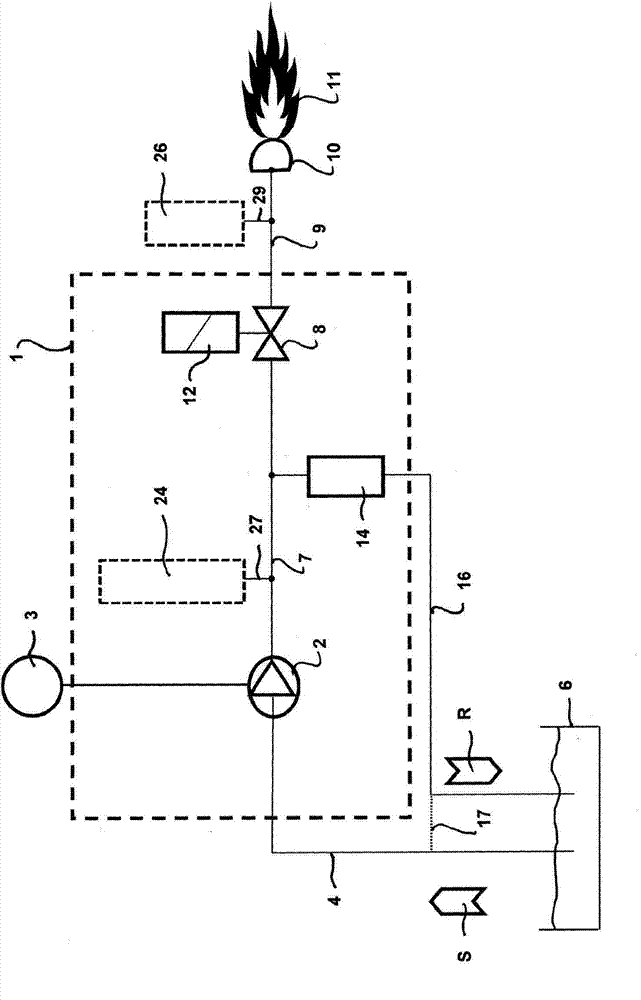
[0035] Both figures show a fuel pump 1 , whose displacement element 2 is driven by a motor 3 , and is admittedly preferably a gear pump, but could alternatively be any other type of pump. The motor 3 may be an independent unit as shown, or may be integrated into the fuel pump 1 .

[0036] The fuel pump 1 draws fuel from a fuel tank 6 by means of a suction line 4 , as indicated by the arrow S .

[0037] On the pressure side of the displacement element 2 of the fuel pump 1 there is firstly a conduit 7 inside the pump which leads to a shut-off device in the form of a shut-off valve 8 and adjoins a further conduit 9 which A conduit 9 feeds fuel to spray nozzles 10 through which the fuel is injected into a combustion chamber (not further shown) to be combusted there into a flame 11 .

[0038] The shut-off valve 8 is actuatable by means of a solenoid valve 12 and is intended to be c...


PUM


Abstract

The invention relates to a heating device operated with liquid fuel, having a fuel pump (1) that comprises a displacement element (2) and is used to suction the liquid fuel out of a tank (6) and feed it to a pressure-conducting region (7, 9), in which an elevated pressure defined by a pressure regulator (14) exists and which transmits the fuel to an atomizer nozzle (10), from which it exits into a combustion chamber to form a burner flame (11). In order to avoid interruptions of operation, the pressure-conducting region (7, 9) comprises at least one additional volume (20, 22), the size of which is selected such that the pressure drop occurring in the pressure-conducting region (7, 9) during suction of gas bubbles does not lead to a lasting interruption of fuel delivery by the fuel pump (1). The additional volume (20) can be integrated directly into the pump or the additional volume (22) can be integrated into the nozzle pipe.

Description

technical field [0001] The invention relates to a heating device operating with liquid fuel of the type set forth in the classification part of claim 1, and also to a fuel pump suitable for such a heating device. Background technique [0002] In the following, the term "conduit" is used to denote a wide variety of hollow spaces and hollow bodies capable of serving as flow paths for fluids, in particular liquids, and having at least one feed for this purpose opening and at least one discharge opening. In addition to tubular conduits, they also include, for example, solid body through holes of any external shape, channels closed on all sides except the feed opening and discharge opening, etc. The term "conduit area" is used to denote a plurality of such conduits which are or can be connected together in flow relationship and which can also be connected to one or more boreholes or grooves which or The groove is of a blind hole-like configuration, ie has only one connection op...

Claims


Application Information

Patent Timeline
IPC IPC(8): F23K5/04F23K5/14F23N1/00F23N5/24F23D11/24B60H1/22
CPCF23K5/142F23N1/005F23N1/007F23N5/247F23D11/24B60H2001/2284F23K5/04F23N2235/30F23N2241/14F23N2239/06F23K5/14
Inventor 尼科·索帕
Owner 斯飞乐有限责任公司
Why Eureka
Try Eureka