
Variable stiffness tension device and working mode thereof

A technology for tensioning devices and working methods, which can be used in transportation and packaging, tracked vehicles, motor vehicles, etc., and can solve problems such as insufficient spring stiffness

Inactive Publication Date: 2015-07-01
SANY HEAVY MACHINERY
View PDF12 Cites 2 Cited by
  • Summary
  • Abstract
  • Description
  • Claims
  • Application Information

AI Technical Summary

Problems solved by technology

[0005] The purpose of the present invention is to provide a variable stiffness tensioning device and its working method to solve the problem that the existing tensioning device has only one spring, resulting in insufficient spring stiffness

Method used


Image

  • Variable stiffness tension device and working mode thereof
  • Variable stiffness tension device and working mode thereof
  • Variable stiffness tension device and working mode thereof

Examples


Embodiment approach

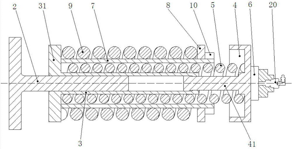
[0025] In further embodiments of the present invention, please continue to refer to image 3 shown. One end of the cylinder 3 has a circular boss 31 , and the piston rod 2 is telescopically close to the end of the cylinder 3 with the boss 31 , so that the piston rod 2 can expand and contract relative to the boss 31 of the cylinder 3 .

[0026] In a further embodiment of the present invention, there is a support rod 41 in the center of the support base 4, and the support rod 41 telescopically penetrates the other end of the opposite boss 31 of the cylinder 3, so that the support base 4 can be telescopically connected to the cylinder through the support rod 4. 3 to approach or move away from the positioning plate 8.

[0027] In a further embodiment of the present invention, one end of the spring 5 with a small stiffness is close to the inner end surface of the boss 31 , and the other end of the spring 5 with a small stiffness is close to the inner end surface of the support sea...


PUM


Abstract

The invention discloses a variable stiffness tension device. The variable stiffness tension device comprises a piston rod, a support seat, a small stiffness spring, a small locking nut, a sleeve, a locating plate, a large stiffness spring and a large locking nut, wherein the piston rod penetrates through one end of a cylinder barrel in a telescopic mode, the support seat penetrates through the other end of the cylinder barrel in a telescopic mode, the small stiffness spring is arranged on the outer side end surface of the cylinder barrel in a sleeving mode, the small locking nut is connected with the support seat, the sleeve is arranged on the outer side end surface of the small stiffness spring in a sleeving mode, the locating plate is fixedly arranged at the end of the sleeve in a sleeving mode, the large stiffness spring is arranged on the outer side end surface of the sleeve in a sleeving mode, and the large locking nut is connected with the locating plate. By using the variable stiffness tension device, when the borne load is smaller, the external force is transferred to the piston rod, the piston rod transfers the force to the support seat and the small stiffness spring, and the small stiffness spring plays a buffer role; when the borne load is gradually increased, the support seat makes contact with the locating plate, the locating plate transfers the load to the large stiffness spring, and the large stiffness spring and the small stiffness spring jointly bear the load.

Description

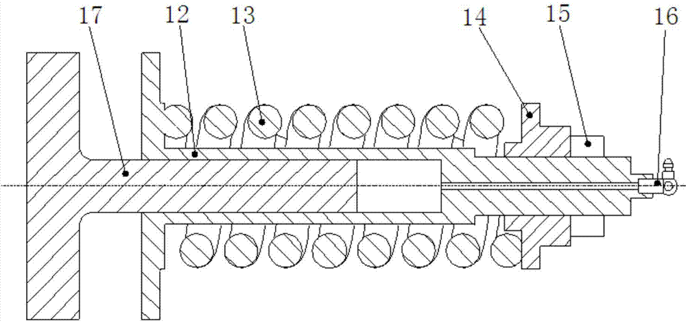
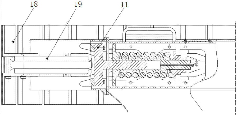
technical field [0001] The invention relates to the technical field of a tensioning device of an excavator, in particular to a tensioning device with variable stiffness and its working method. Background technique [0002] The tensioning device of the excavator is an important part of the traveling device that connects the guide wheels and the lower frame. figure 1 is a schematic diagram of an existing variable stiffness tensioner, figure 2 For the installation diagram of the existing variable stiffness tensioner, please refer to figure 1 and figure 2 shown. Existing tensioning device 11 is usually made up of cylinder block 12, spring 13, bearing 14, lock nut 15, oil filling valve 16 and piston rod 17 etc. The purpose of adjusting and keeping the crawler belt 18 tensioned and preventing the crawler belt 18 from falling off is achieved by adjusting the amount of butter in the oil cylinder. When the crawler moving component encounters an obstacle, the guide wheel 19 can...

Claims


Application Information

Patent Timeline
IPC IPC(8): B62D55/30
CPCB62D55/30
Inventor 裴拂晓肖丙喜刘鹏飞
Owner SANY HEAVY MACHINERY
Learn More