Valve stem and valve sleeve of a steam turbine control valve

A technology for regulating valves and steam turbines, applied in valve details, valve devices, mechanical equipment, etc., can solve problems such as increasing user maintenance costs, affecting the stability, reliability, safety and economy of steam turbines, and increasing wear resistance. , reduce friction, reduce the effect of steam leakage

Inactive Publication Date: 2017-06-06
HANGZHOU DIANZI UNIV
View PDF4 Cites 1 Cited by
  • Summary
  • Abstract
  • Description
  • Claims
  • Application Information

AI Technical Summary

Problems solved by technology

[0004] The wear and leakage of the control valve stem directly and seriously affect the stability, reliability, safety and economy of the steam turbine, further increasing the maintenance cost of the user

Method used


Image

  • Valve stem and valve sleeve of a steam turbine control valve
  • Valve stem and valve sleeve of a steam turbine control valve
  • Valve stem and valve sleeve of a steam turbine control valve

Examples


Embodiment Construction

[0032] Below in conjunction with accompanying drawing, the present invention is described in further detail:

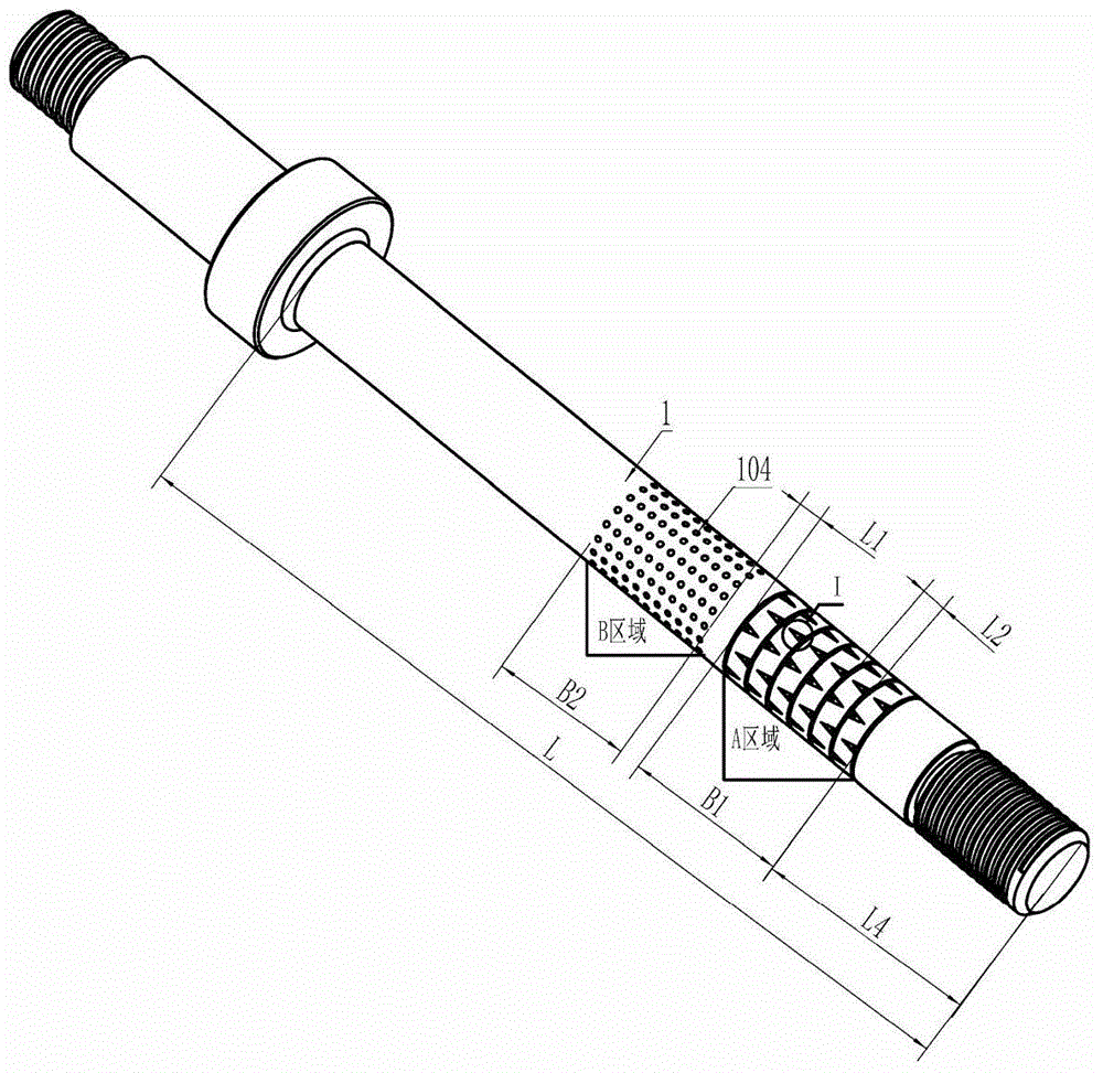
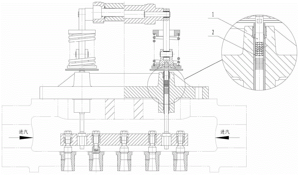
[0033] like figure 1 , figure 2 As shown, the valve stem 1 has A region and B region in the matching region of the valve sleeve 2, and the B region is at the lower end of the A region; the A region is a dynamic pressure balance region, and the B region is a hydrophobic region, wherein the A region Set at the position where the distance L4 from the outlet end of the valve stem accounts for 1 / 8 to 1 / 6 of the total length L of the valve stem; the distance L1 between the A area and the B area is 10-20mm; the width B1 of the A area accounts for the total length of the valve stem 1 / 6~1 / 5 of the total length of the valve stem, and the width B2 of the B area accounts for 1 / 6~1 / 5 of the total length of the valve stem.

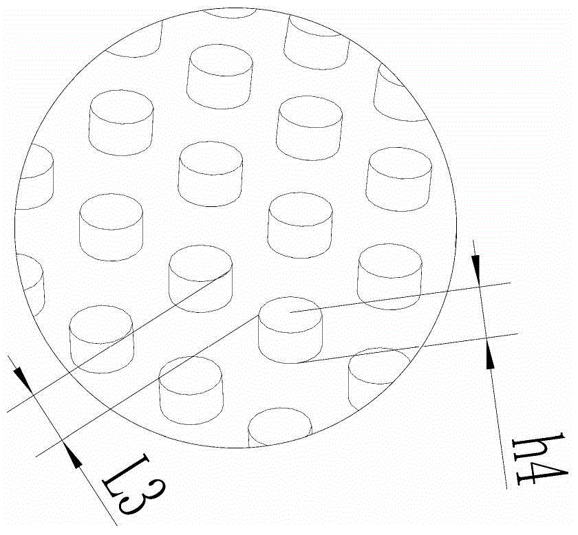
[0034] The area surface of the dynamic pressure balance area is provided with a valve stem seal liquid storage tank 103, and a dynamic pressure balance tank...


PUM


Abstract

The invention discloses a valve rod and a valve bush of a turbine regulating valve. The area segment, matched with the valve bush, of the valve rod is provided with an area A and an area B, and the area B is located at the lower end of the area A. The area A is a dynamic pressure balancing area, the area B is a hydrophobic area, and the area A is arranged at the position, 1 / 8 to 1 / 6 of the total length of the valve rod away from the outlet end, of the valve rod. The distance between the area A and the area B is 10 mm to 20 mm. The width of the area A accounts for 1 / 6 to 1 / 5 of the total length of the valve rod, and the width of the area B accounts for 1 / 6 to 1 / 5 of the total length of the valve rod. The valve bush is of a split structure, and micro-convex or micro-concave areas C of a superhydrophilic surface texture are arranged in the valve bush and the matched area segment of the area A. According to the valve rod and the valve bush, friction can be reduced, the abrasion resisting performance can be increased, the stability of the valve rod can be improved so that the multi-stage sealing function can be achieved, and based on the flow resistance effect, steam leakage is further reduced.

Description

technical field [0001] The invention relates to steam turbine fittings, in particular to a valve rod and a valve sleeve of a steam turbine regulating valve. Background technique [0002] The control valve is an important steam distribution executive component of the steam turbine. It adjusts different intake air volumes by adjusting the valve stem up and down. Regulating valves operate in a high-temperature and high-pressure steam environment for a long time, requiring the valve to have good sealing and stability to prevent leakage of high-quality steam from the valve, resulting in loss of efficiency and even safety accidents. [0003] In actual operation, clearance fit is used between the valve stem and the valve sleeve, and its leakage is unavoidable. In order to reduce steam leakage, most of the solutions are now using elastic packing or other wear-resistant material packing to reduce the gap between the valve stem and the valve sleeve as much as possible. Although it pl...

Claims


Application Information

Patent Timeline
Patent Type & Authority Patents(China)
IPC IPC(8): F16K51/00
CPCF16K31/44
Inventor 许静倪敬吴参蒙臻
Owner HANGZHOU DIANZI UNIV
Why Eureka
Try Eureka