
Optical fiber mold stripper and method for manufacturing optical fiber mold stripper

A manufacturing method and technology of a stripper, which are applied in the directions of light guides, optics, instruments, etc., can solve the problems of large damage, can not effectively improve the output power of fiber lasers, increase the length of optical fibers, etc. The effect of increasing the output power

Active Publication Date: 2016-03-02
MAXPHOTONICS CORP
View PDF4 Cites 0 Cited by
  • Summary
  • Abstract
  • Description
  • Claims
  • Application Information

AI Technical Summary

Problems solved by technology

In this pump mode, the attenuation of the pump light in the fiber is an exponential mode. When the pump light attenuates to a certain extent, increasing the fiber length not only cannot effectively improve the output power of the fiber laser, but also increases the cost.
Therefore, there is an optimal value for the length selection of the active fiber, but the limited length of the active fiber means that part of the pump light cannot be absorbed and becomes useless light
If this part of useless pump light continues to propagate in the optical fiber, it will damage the subsequent devices and become harmful light. Especially for high-power fiber lasers, the power of the remaining pump light is often high, and its destructive effect is also great. , therefore, the fiber laser must take effective measures to leak this part of the remaining pump light

Method used


Image

  • Optical fiber mold stripper and method for manufacturing optical fiber mold stripper
  • Optical fiber mold stripper and method for manufacturing optical fiber mold stripper
  • Optical fiber mold stripper and method for manufacturing optical fiber mold stripper

Examples


Embodiment Construction

[0024] The following will clearly and completely describe the technical solutions in the embodiments of the present invention with reference to the drawings in the embodiments of the present invention.

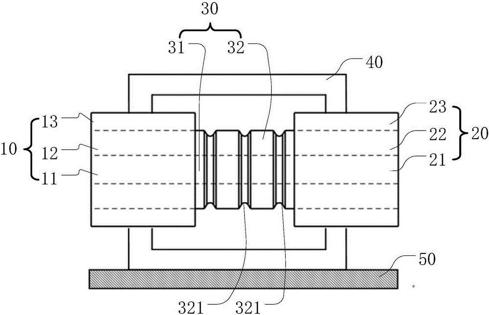
[0025] refer to figure 1 , is an optical fiber stripper 100 provided in an embodiment of the present invention. The fiber stripper 100 is located between the fiber laser and the laser output fiber, and is used to strip the residual pump light of the fiber laser, so as to ensure that the fiber laser only outputs laser light, so as to improve the laser transmission quality of the fiber laser.

[0026] The fiber stripper 100 includes an input end 10 , an output end 20 and an attenuation area 30 . The input end 10 includes a first core 11 , a first inner cladding 12 and a first outer cladding 13 . The output end 20 includes a second core 21 , a second inner cladding 22 and a second outer cladding 23 . The attenuation region 30 includes a third core 31 and a third inner cladding...


PUM


Abstract

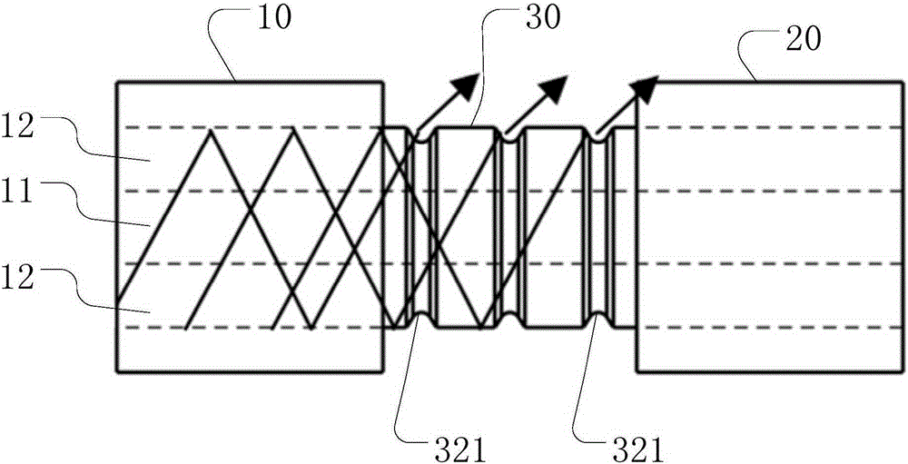
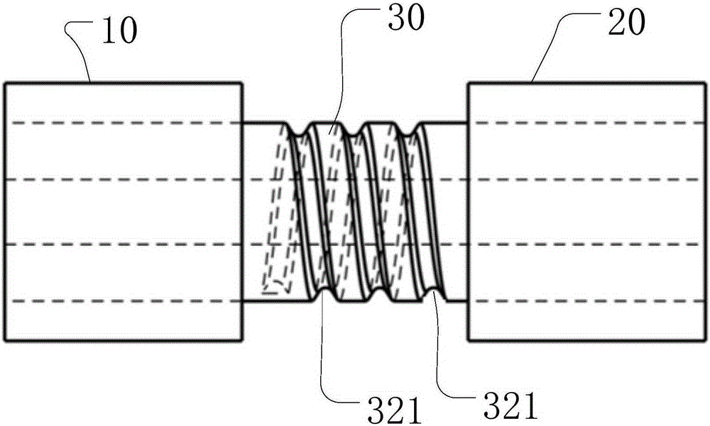
The invention discloses an optical fiber mode stripper. The optical fiber mode stripper comprises an input end, an output end and an attenuation area. The input end comprises a first fiber core, a first inner cladding layer and a first outer cladding layer. The output end comprises a second fiber core, a second inner cladding layer and a second outer cladding layer. The attenuation area comprises a third fiber core and a third inner cladding layer. The third fiber core is connected between the first fiber core and the second fiber core, and the third inner cladding layer is connected between the first inner cladding layer and the second inner cladding layer and exposed between the first outer cladding layer and the second outer cladding layer. A plurality of grooves are formed in the third inner cladding layer and formed by extending along the circumferential direction of the third inner cladding layer. The invention further discloses a manufacturing method of the optical fiber mode stripper. The optical fiber mode stripper has the advantages that pump light output by an optical fiber laser device can be attenuated effectively, transmitting quality of the laser in an optical fiber is improved, output power of the optical fiber laser device is increased, and output quality of the optical fiber laser device is improved.

Description

technical field [0001] The invention relates to the field of fiber lasers, in particular to an optical fiber mold stripper and a manufacturing method of the optical fiber mold stripper. Background technique [0002] Fiber lasers are all made of double-clad fibers. The pump light is mainly transmitted in the inner cladding, and is coupled to the core during transmission to be absorbed and form a new laser in the core. In this pump mode, the attenuation of the pump light in the fiber is an exponential mode. When the pump light attenuates to a certain extent, increasing the fiber length not only cannot effectively improve the output power of the fiber laser, but also increases the cost. Therefore, there is an optimal value for the length selection of the active fiber, but the limited length of the active fiber means that part of the pump light cannot be absorbed and becomes useless light. If this part of useless pump light continues to propagate in the optical fiber, it will d...

Claims


Application Information

Patent Timeline
Patent Type & Authority Patents(China)
IPC IPC(8): G02B6/245
Inventor 居剑蒋峰
Owner MAXPHOTONICS CORP
Learn More